HP Cluster Platform Quadrics QsNetII Interconnect Part Number: A-CPQIG-1A May 2005 Revision/Update Information: Version 1.1 Product Version: HP Cluster Platform This manual describes how to install, operate, and manage the Quadrics QsNetII interconnect used in certain models of HP Cluster Platform. It also provides instructions for replacing interconnect components and describes the available diagnostics.
© Copyright 2005 Hewlett-Packard Development Company, L.P. Quadrics® and QsNetII™ are trademarks or registered trademark of Quadrics, Ltd. The information contained herein is subject to change without notice. The only warranties for HP products and services are set forth in the express warranty statements accompanying such products and services. Nothing herein should be construed as constituting an additional warranty. HP shall not be liable for technical or editorial errors or omissions contained herein.
About This Manual This manual describes how to install, operate, and manage the Quadrics® QsNetII™ interconnect that is used as a system interconnect for certain models of HP Cluster Platform. Read this entire manual before beginning the installation. Familiarity with the general sequence of installation steps can save time and prevent problems.
Chapter 8 Explains how to install the QS32A 16/32-port chassis and install field-replaceable modules in the interconnect chassis. Chapter 9 Provides procedures for postinstallation configuration and installation verification of the interconnect. Chapter 10 Identifies the signal LEDs on Quadrics interconnect module, and describes the status information provided by the LEDs. Chapter 11 Explains how to access and use the interconnect control menu.
Related Documentation The following documents may be useful references when you are installing and administering the HP Cluster Platform. Cluster Component Documentation A cluster is mostly assembled from existing HP components that each have their own documentation set. Two full sets of documentation for each type of component are included with the cluster when it is delivered.
HP welcomes your comments on this manual. Please send your comments and suggestions by E-mail to readers_comment@zk3.dec.com.
Safety Considerations To avoid bodily harm and damage to electronic components, read the following safety and comfort guidelines before unpacking and configuring the cluster components. Heed the following additional warnings and refer to the Cluster Platform Overview and Site Preparation Guide to obtain specific information on safety issues. Before working on any cluster components, be sure to read the component-specific safety information that is in the documentation provided for each component.
Refer to the specifications section of the component documentation to find the weight of a component. Removing and Replacing Component Covers For your safety, never remove the cover from a cluster component without first disconnecting the power cord from the power outlet and removing any connection to a telecommunications network. If a Power Protection Device is fitted to your system, you must shut down the computer using its on/off switch, then remove the power cord before removing the component’s cover.
Recycling Shipping an integrated cluster generates far less packaging than the individual components that it contains. However, large clusters use a substantial amount of packaging material that is not reusable. The bulk of the packaging material is recyclable, and is labeled as such. You should plan on providing a number of dumpsters into which this packaging can be sorted and recycled. HP has a strong commitment to protecting the environment.
1 Overview of Quadrics-Based Clusters A cluster is a set of independent computers combined into a unified system through system software and networking technologies. An overview of the generic HP Cluster Platform architecture is provided in the Cluster Platform Overview.
Table 1-1: Terminology (cont.) Cluster Terminology Component link QSNetII 12x EOP link cable, providing the physical link between the interconnect switch cards and the host-bus adapter in the node. Also used for the interconnect-to-interconnect links in federated clusters. management port See controller card. module A component that you install in the interconnect chassis to create a specific interconnect configuration. Switch cards, clock cards, fan trays, and power supplies are pluggable modules.
Consult the operating system documentation for information about the power-on and boot sequence. 6. Optionally, entering license information to unlock the HP Cluster Platform software. 7. Performing basic tests and running diagnostics (where available) to ensure correct assembly. 8. Troubleshooting the cluster, if necessary. 9. Configuring the software, as described in the optional operating system software documentation.
_______________________ Note _______________________ The clock distribution cables are very similar to the Ethernet cables; both are fitted with RJ45 connectors. When cabling the network, ensure that the correct cables are used The multicore copper serial cables used in the interconnect network are susceptible to faults if damaged by mishandling. These faults might cause operational errors in the cluster that are difficult to detect and correct.
• Do not use a cable assembly if you suspect that it has been damaged. • Do not try to move a system by pulling on its cables. 1.3.2 General Cable Routing Guidelines Keep the following rules in mind when installing other cables, such as connections from the cluster to your local area network: • If possible, route cables in a manner that allows the shortest overall cable length. • Keep signal cables away from power cables.
interconnects must be configured differently as node-level and top-level interconnects. The interconnects are linked into a hierarchy to create all levels of the fat tree network topology. Such clusters are described as federated. The type of cluster is determined by the customer’s order, and is specified by the bill of materials (BOM) generated by that order.
cabling links are specified as secondary destinations in the cabling tables. 11. Determine whether any of the supplemental rules apply, according to the cabling tables for your model and configuration of HP Cluster Platform. 12. Using the appropriate Cabling Tables as a worksheet, cable the cluster according to the cabling chart and supplemental rules. See Section 7.6 for information on connecting cables. (Some cluster configurations might specify optional connections). 13.
2 Quadrics Interconnect Overview A high-speed interconnect switch supporting a private network is the core component in the HP Cluster Platform cluster. Within an HP Cluster Platform cluster, all application and utility nodes have a direct connection to the switch. A connection for the control node is optional. A scalable, high performance interconnect enables you to network industry-standard servers together to form a high-speed cluster.
• Ethernet cables connecting the interconnect to the cluster’s internal Ethernet networks, enabling access to built-in diagnostics and management programs. • A clock distribution (QM580) box for generating a global clock source in a federated network. • Shielded CAT–V clock distribution cables join all interconnects in a federated network to a common clock synchronization source.
A federated network, (greater than 128 nodes) can support a theoretical maximum topology of 4096 nodes, although the actual maximum is constrained by the limits of physical connection, such as cabling constraints. For 256 nodes or greater, interconnects are connected in four stages; for larger networks, the interconnects are connected in five stages. _________________________ Note _________________________ HP Cluster Platform supports only the number of nodes specified for any given release.
2.3 Federated Networks To scale the interconnect network for clusters with more than 128 nodes, the enclosure is configured as either a node-level interconnect (NLI) or as a top-level interconnect (TLI). Node Level Interconnect (NLI) When fully populated, an NLI has ports for up to 64 nodes plus 64 uplinks to connect to the next stage in the switch network. The NLI contains up to 4 QM501 switch cards and 4 QM502 switch cards.
• The letter N or T indicates the type of interconnect: N for node-level; T for top-level. • The integer ICNumber is the interconnect’s identification number based on its position in the hierarchy. The numbering of both node-level and top-level interconnects starts at 0 (zero). Table 2-1 shows the range of interconnect names depending on the number of nodes in the cluster.
3 128-Port Interconnect Modules The 128–port QS64A chassis in an HP Cluster Platform is modular, enabling the installation of different combinations of midplanes and cards to support varying cluster configurations. Configurations are determined by the number of nodes in the cluster, the density of the nodes, and other options such as connecting the cluster control node to the interconnect. Clusters are preconfigured before delivery.
3.1 QM500 Host Bus Adapter (HBA) The QM500, shown in Figure 1-3, is a high performance network interface card, based on the Quadrics Elan communications device. Figure 3-1 shows the card. Figure 3-1: QM500 Host Bus Adapter (HBA) PCI Card Each node in a cluster requires at least one QM500. The card provides a single high speed link for connection to an interconnect switch card port. The QM500 is a Universal, short, 64-bit PCI X card which conforms to PCI X 1.
The QM503 controller card distributes the master clock to all cards in the interconnect. In addition, it has an embedded processor for controlling and monitoring the interconnect via a login by local terminal or remote network connection. For clusters with greater than 128 nodes, the interconnect enclosure is configured as a node-level interconnect (NLI) or a top-level interconnect (TLI). These configurations require difference midplanes and combinations of QM501 and QM502 switch cards.
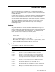
3.2.2 Port and Slot Numbering Figure 3-2 shows how the front slots are numbered in an enclosure. At the front of the switch, there are 5 vertical slots: 4 slots for the switch cards and one slot for the secondary QM503 controller card. These slots are numbered from right to left: 4 and 5, the secondary QM503 controller card, Ctrl B, and then 6 and 7. The 5 vertical slots at the rear of the switch can be populated with up to 4 switch cards.
Figure 3-3: Interconnect, Rear View with Slot Numbering Slo t0 Slo t1 Fa nA /C trlA Slo t2 Slo t3 Fan A/CtrlA Slot 0 Slot 1 Slot 2 Slot 3 HPTC-0028 3.2.3.2 Interconnect Configuration for Federated Clusters For clusters with greater than 128 nodes, the interconnect enclosure is configured as a node-level interconnect (NLI) or a top-level interconnect (TLI). These configurations require different midplanes and combinations of QM501 and QM502 switch cards.
3.2.3.2.1 Node-Level Interconnect (NLI) Node level interconnects use the 3X-CS5A0-AF midplane. 4 QM502 switch cards are inserted in slots 0 through 3 in the rear of the enclosure. 4 QM501 switch cards are inserted in slots 4 through 7 in the front of the enclosure. Each of the QM501 cards has 16 link ports, making 64 ports in a fully populated enclosure. The port numbers on the QM501 and QM502 cards start at the top and are numbered 0-15. Node level interconnects use the 3X-CS5A0-AF midplane.
Figure 3-4: QM501 Switch Card Each of the 16 downlinks of the first stage of switches connects to a QM500 network adapter. The 4 uplinks of each Elite in the second stage of switches connect to QM502 downlinks. 3.3.2 QM502 Switch Card The QM502, shown in Figure 3-5, is a switch card containing four Elite switch components. It provides 16 ports to implement the third stage in the fat tree topology.
Figure 3-6: QM511C Switch Card Each of the 16 downlinks of the first stage of switches connects to a QM500 network adapter. 2 of the 4 uplinks of each Elite in the first stage connect to 8 downlinks from the 2 second stage Elites. The 8 uplinks of the second stage Elites connect to the top level Elite, one link to each of the 8 top level switches across all 8 QM511C modules. 3.3.4 QM511L Switch Card The QM511L, shown in Figure 3-7, is a switch card containing a single Elite switch components.
The callouts in this figure identify the following features: 1. LED status indicators. 2. The COM 1 port. Use this port to make a local telnet connection from a PC or laptop when configuration an interconnect. When the internet is configured with an IP address and connected to the network, you can access it from your LAN. 3. Mouse and Keyboard. Use this port to make a local dumb terminal connection when configuration an interconnect. You must also connect a monitor to the VGA port (5). 4.
2. Clock in ports. Clock in A is the top port, Clock in B is the bottom port and is not used. 3. Mode select switch. 4. Power switch. 5. Fuse. 6. Power inlet. By linking two or more clock boxes together, it is possible to provide clock signals for more than 24 interconnects. The QM580 has a 1 U high, 170 mm deep, screened enclosure, suitable for mounting in standard 19 inch (600 mm) equipment racks. The main input current to the QM580 is less than 0.30 A.
6. Repeat steps 1-5 until all interconnect controller cards are cabled to their respective clock boxes. 7. Connect the synchronization cable between the clock boxes, as specified in the cabling tables. 8. Ensure that the clock mode switches are set to master for clock box A and Slave for clock box B. 9. The post-installation verification procedure includes a clock verification task. Ensure that the complete clock network is visible and the clock has a frequency of 665 MHz (plus or minus 0.5 MHz).
4 16/32-Port Interconnect Smaller clusters are optionally built using the Quadrics model QS32A 16/32-port interconnect. The following information is provided for this component: • An overview of the interconnect is provided in Section 4.1 • Instructions for cabling the 16/32-port interconnect are provided in Section 4.2 • An explanation of the 16/32-port interconnect signal LEDs is provided in Section 4.3 4.
3. A single Infiniband port of the 16 ports or 32 ports in the switch card module, with its integrated EMI shielding. 4. Port status 3-LED array (green, amber, and red). 5. Controller card status array (green, green, and red). 6. Reset button (recessed to prevent accidental operation). 7. The connection ports for the controller card. These ports are defined in a later section. 8. Captive screws that secure the switch card module in the interconnect chassis (2 of 4 screws indicated).
• Install spring connector clips on all ports in use. Ensure that all the spring fingers are in contact with the cable connector housing. Replace the clips if they show any signs of damage. 4.2.1 Connecting Cables to the Interconnect Use the following procedure to install cables: 1. Undo the knurled bolts screws securing the cable management upper retainers. 2. Lift the cable management upper retainers and insert the link cables into the channels. 3.
the correct power outlet ensures that the rack’s power draw is balanced across the power distribution units. Connect the power cable to the IEC60320 appliance inlet on the 16/32-port interconnect. When powered up, normal operation of the fan and PSU Module is indicated by the illumination of the green LED labeled Power. b. Controller Ethernet cable. c. Terminal and keyboard, if you plan to perform local configuration tasks.
Color Interpretation Normal Status Alternate Status Green Link function Illuminated if the link is functioning. Unlit if the link has a problem or is disconnected. Yellow Link activity Illuminated or flashing if data Unlit if no data is passing traffic is passing through the link. through the link. Red Link error Off. On – there is an error on the link.a a The red LED illuminates after you connect a link to a node because the link resets when the node boots.
5 QM500 Network Adapter This chapter provides a generic installation procedure for the QM500 network adapter in a node and how to service the QM500. It should be read in conjunction with the instructions supplied with the node computer for fitting a PCI X card. See the Servers and Workstations Guide for specific instructions for certain models of HP servers. The successful conclusion of the installation process results in the illumination of the green LED on the QM500 network adapter.
8. Connect the link cable from the faceplate of the QM500 to the port on the interconnect. 9. Power up and reboot the node. 5.2.2 General Instructions for Removing the QM500 Network Adapter The procedure for removing a QM500 is as follows: 1. Halt and power off the system. 2. Disconnect the link cable from the faceplate of the QM500. 3. Remove the appropriate side panel. 4. Remove the screw which fastens the faceplate of the QM500 to the system’s chassis. 5.
6 QM580 Clock Distribution Box This chapter describes the installation, operation, and maintenance of the QM580 clock distribution box. The QM580 clock distribution box provides a global, external clock source for a federated network of interconnects. 6.1 Replacing a QM580 Clock Distribution Box Before replacing a QM580 clock distribution box, ensure that the federated network is using an alternative clock source.
6. Determine the appropriate rack U-location for your model of HP Cluster platform. (This is usually determined by the original shipment configuration of your cluster, or by the documentation that accompanies an upgrade kit). 7. Clip four M6 cage nuts into the back of the rack at the U-location, using all three of the square mounting holes at the U-location. 8. Slide the new or replacement QM580 into the rack and align the chassis mounting holes with the cage nuts that you inserted in Step 7. 9.
6.3 Powering Up a QM580 Clock Distribution Box The QM580 clock distribution box uses a Universal power supply operating in the range 90-254 V AC (61-49 Hz). Power is supplied through a standard IEC320 socket on the front panel. To power up a QM580 clock distribution box, perform the following steps: 1. Connect the power cable to a grounded AC power outlet and to the IEC320 power socket on the front panel of the QM580 clock distribution box. 2.
7 Installation and Maintenance of the 128-Port Interconnect This chapter describes how to install modules and service the 128–port interconnect. The installation procedures are similar for all interconnect configurations used in the HP Cluster Platform. Where the procedures differ, the switch card (module) or midplane type is mentioned explicitly. 7.
A rack mounting kit is supplied with each interconnect. It has three sets of components with fasteners as follows: • An enclosure tray • Four tray slides (two front and two rear) • Two mounting brackets • Fasteners: - 12 cage nuts, washers, and machine screws to attach the rail kit to the rack columns. - 16 machine screws to attach the brackets to the interconnect enclosure. - 6 cage nuts, washers and screws to attach the brackets to the rear rack columns.
Use the following procedure to install the enclosure in the rack: 1. Unpack the interconnect enclosure and the rack mounting kit, ensuring that all components and fasteners are present. 2. Attach a bracket to each side of the interconnect enclosure using the 16 screws supplied, setting the position of the bracket as shown in Figure 7-2. Figure 7-2: Attaching the Bracket to the Enclosure 0 25.0 2 29.1 2 28.1 3.
6. The tray can move freely on the slides. Slide it all the way to the rear of the rack. _______________________ Note _______________________ The tray might move as you are lifting in the interconnect enclosure. Hold the tray as you slide the enclosure forward. 7. Remove the protective covers and the nuts and washers from the two threaded studs at the base of the interconnect enclosure. Retain these fasteners for later use. 8.
7.3.1 Installing a QM501 or QM502 Switch Card Color-coded keys, known as midplane polarizing keys, are fitted to the switch cards and to the midplane of the interconnect. These keys prevent the switch cards from being fully inserted in an incorrect slot. Polarizing keys function as follows: • QM501 cards are normally installed in slots 0-3. Some interconnect configurations contain QM54X midplanes. In these configurations you can install QM501 switch cards in slot positions 4-7.
2. Unpack the QM511C modules and insert them in the vertical slots numbered 0-7 in the interconnect enclosure. 3. Start with the far left slot on the rear (slot 0) and then fill slots from left to right. 4. Snap the QM511C in place by applying force evenly to the two latches. 5. When the QM511C is located, secure the two latches using the captive screws. 6. When the rear slots are full, move onto the far right slot on the front (slot 4) and fill slots from right to left. 7.
depending on whether redundant operation is required for the end user installation. Note that if only one QM503 is fitted (no redundancy), use slot Ctrl A only. 7.3.5.1 Replacing a QM503 controller Card You can replace QM503 controller cards without powering down the interconnect provided that two modules are fitted to provide redundancy. The procedure to replace a QM503 controller card is as follows.
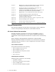
Figure 7-6: Replacing the Lithium Battery a QU t" Ne Qs ics Dr U PS A Fan B/Ctrl B U PS B Batter and Holder HPTC-0034 Use the following procedure to replace the battery: 1. Remove the QM503 controller card from the interconnect. 2. Carefully slide the Lithium battery from under the metal clip holding it in place on the QM503 and fit the replacement, ensuring the positive side of the battery is face up. 3. Replace the QM503 in the interconnect. 7.3.5.
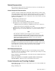
unit. A QM566 power supply blank must be fitted to slot B if only one QM561 power supply unit is fitted. Figure 7-7: Inserting or Removing a Power Supply aD QU t" Ne Qs s ric U PS U PS A PSU A B Latch HPTC-0033 Install the QM561 power supply units as follows: 1. Unpack the QM561 power supply units and remove the blank from the interconnect enclosure, if fitted. 2. If only fitting one QM561 power supply unit, insert it into slot PSU A and fit slot PSU B with a QM566 power supply blank.
Use the following procedure to replace a power supply: ________________________ Caution _______________________ If you remove a QM561 while the interconnect is powered up, do not leave the system running unattended and do not insert anything other than a replacement QM561 in the vacant slot. 1. Unpack the new QM561 power supply unit, keeping the packaging materials. 2. Check the status of both the QM561 to be replaced and the QM561 that is to remain in the interconnect.
3. When a QM562 fan tray is fully inserted, the two slam latches will clip shut automatically and secure the QM562 in place. Replace a fan tray as follows: ________________________ Caution _______________________ The interconnect will operate normally for up to 120 seconds without fan cooling. Service personnel must ensure that the replacement task is completed within this time. Prepare the new fan tray before removing the existing tray. 1.
functioning, you can swap the other out for maintenance with no disruption to the operation of the interconnect. When powered up, normal operation of each QM561 power supply unit is indicated by the illumination of the following LEDs: Label Color Status AC OK Green On DC OK Green On Fault Red Off Over Temp Red Off 7.3.
2. Verify that the Main menu is displayed, pressing Return to redraw the screen as necessary. 3. Select menu option Set Module Mode by pressing 4 followed by Return. 4. In response to the prompt Set Federated "y" or "n", press y for a federated switch or n for a standalone Switch, followed by Return. 5. In response to the prompt Set Redundant "y" or "n", press y if a second QM503 is, or will be, installed in slot Ctrl B, otherwise press n followed by Return. 6.
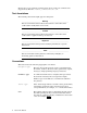
Figure 7-10: Connecting Link Cables Ensure that the connector fits the socket within a tolerance of 10 degrees of the horizontal a QU 10 t" Ne Qs ics Dr U PS A 10 U PS B Cable Connector Socket Cover HPTC-0029 7.6.1 Connecting QM581 Link Cables When linking QM501, QM502 and QM511C modules together, use QM581 link cables which are available in a range of lengths. The procedure for connecting QM581 link cables to a QM501, QM502 or QM511C is as follows: 1.
4. When all of the required cables are connected, fit a QM574 EMC shielded connector cover to all unused ports. 7.6.2 Disconnecting Link Cables Remove links as follows: 1. If you are replacing a bad link, route the replacement cable first. _______________________ Note _______________________ You might not want to go to the trouble of completely removing a bad cable unless it is to be returned for replacement. In this case, mark the cable as bad and route the new cable. 2.
7.6.5 Electromagnetic Interference (EMI) Adhere to the following guidelines to ensure that the interconnect meets its EMI specifications when operating: 1. All clock I/O connections must be made using the specified QM584 CAT-VE double-screened (foil and braid) cables that are identified by the correct FRU part number. Do not use any other CAT-VE cables. 2. All network I/O connections must be made using specified cable assemblies that are identified by the correct FRU part number. 3.
Figure 7-11: Typical Midplane kit Components Midplane Wiring Looms (2) U PS U PS A B Captive Fasteners (22) Original Midplane Rear View Midplane Handles (2) Switch Off and Remove Power Cords Rear Protective Cover Replacement Midplane Front Protective Cover Midplane Handles (2) HPTC-0032 2. Ensure that the power to the interconnect is turned off and that the power cables are disconnected. Label and disconnect all cables. 3.
9. Tilt the bottom of the midplane towards you until it will clear the top of the module cage then, keeping it at this angle, slowly and carefully remove the midplane from the interconnect. 10. Take off the midplane handles and fit Midplane protective covers (if supplied with the replacement midplane). 11. Fitting a replacement QM540 or QM542 midplane is the reverse of removal, except that the front cover should be left in place until the midplane is installed in the interconnect.
8 Maintenance of the 16/32-Port Interconnect • Installation of the chassis is described in Section 8.1 • Replacing a fuse in the IEC power inlet is described in Section 8.2. • Replacing a fan and power supply module is described in Section 8.3. • Replacing a switch card module is described in Section 8.4. • Replacing a controller card module is described in Section 8.5. • Replacing the lithium battery in a controller card module is described in Section 8.6.
Table 8-1: 16/32-Port Interconnect Rail Kit Callout Item Description Quantity 1 Front track, which slides into the rear track and mounts on the front rack columns 2 2 Rear track, which mounts on the rear rack columns 2 3 Slide rails that mount on the interconnect chassis 2 4 Cable management slides (Left and right, forming part of the cable management assembly, which slides onto the track).
Figure 8-2: 16/32-port chassis Cable Management Assembly ` _ X ] ^ \ Y Z [ X Y Use the following procedure to first assemble the cable management components: 1. On each cable management slide (callout 1) , screw 2 M4 x 10 mm knurled-head bolts (callout 2) loosely into the two outer holes, giving each bolt only a few turns. 2. Mount the first cable management lower retainer (callout 3) onto the lower set of lugs on the cable management slide.
9. Secure both the cable management upper retainer and the cable management lower retainer to the right hand cable management slide by using an M4 x 10 mm knurled-head bolt. When you have assembled the cable management components, you mount it on the rack kit as shown in . Figure 8-3: Installing the Rack Rails Use the following procedure to assemble the rail kit and install the interconnect in the rack.
6. Fasten the two front tracks to the rack columns by using four screws (two in each column). Do not tighten the screws at this time. (No screw thread should show, but the screws should be loose enough to allow for minor adjustment of the track). 7. Adjust the position of the sliding cable management bracket and tighten all 4 M4 x 10 mm knurled-head bolts to secure it in place. 8.
Figure 8-5: Installing the Chassis in the Rack Front of Rack 12. Tighten all the screws that secure the front and rear tracks. _______________________ Note _______________________ The cable management assembly must support and align the cables and connectors with the Infiniband ports. As part of the cabling procedure, you might need to adjust the position of the cable management assembly so that it adequately supports the cables and also enables easy removal of a cable when required.
6. Let the interconnect run for a few minutes to ensure that the fault was not within the power supply. If the fuse burns out a second time, replace the fan tray and power supply unit as described in Section 8.3. 8.3 Replacing the Fan and PSU Module If the power supply indicator does not illuminate and you do not hear or see the fans running, check the fuse as described in Section 8.2. If the fuse burns out persistently, or the fuse remains good but the fans do not start, replace the fan and PSU module.
8.4 Replacing the Switch Card Module Use the following procedure to replace the switch card module: 1. Unpack the replacement module, retaining all the packaging materials. 2. Switch off the power and disconnect the power cord at the inlet. 3. Disconnect all the cables and remove the interconnect chassis from the rack as described in Section 4.2.2. 4. Remove the Fan and PSU module as described in Section 8.3 and put it aside in a safe location. 5.
Figure 8-8: Controller Module [ Y Z X \ \ \ \ The following features of the controller module are relevant to servicing: 1. The connector for the ribbon data cable. The other end of this cable connects to the switch card module. 2. The power cable connector. 3. The replaceable lithium battery. (SeeSection 8.6). 4. Below the battery is a slot for a replaceable flash memory card that stores the controller firmware. (SeeSection 8.7). 5.
9. Secure the module by replacing the four hexagonal screwlocks and washers. 10. Replace the fan and PSU Module as described in Section 8.3. 11. Reconnect the cables that you disconnected in step 3. Reconnect the power cable. 12. Pack up the defective module using the materials supplied and return it to HP for repair or replacement. 8.6 Replacing the Controller Module’s Battery Replace the battery only with a type CR2032 battery or equivalent.
9 Postinstallation Configuration and Testing This manual describes how to service HP Cluster Platforms employing the Quadrics® QsNetII™ Interconnect. It also describes basic diagnostic procedures you can use to find out whether or not you have correctly configured the components of the cluster and also to troubleshoot the cluster. The first diagnostic that you will perform is a post-installation verification of the assembled cluster.
This manual does not cover diagnostics and troubleshooting for other cluster components, such as servers (used as nodes) or Ethernet network switches. See the hardware documentation for a specific component. Note on Terminology Diagnostics software and interconnect management software is supplied by the interconnect vendor. The command interfaces to the software used the generic term switch to describe the interconnect.
5. • Connect a dumb terminal to the port labelled on the QM503 controller card. Connect a keyboard to the port labeled Mouse Kybd. These ports are shown by callouts 5 and 3 in Figure 10-1. • Connect a PC or laptop to the port labeled COM 1 on the QM503 controller card. Use terminal emulation software to open a connection to the card. The port is shown by callout 2 on Figure 10-1.
can further be determined by the interconnect cabling labels. (See the cabling tables for a description of the labeling syntax). Each interconnect chassis has a unique name that describes its address and location in the network topology. A typical chassis name is QR0N00 and the default TCP/IP addresses are shown in Table 9-1. Table 9-1: Interconnect Names and TCP/IP Addresses TCP/IP Address Interconnect Chassis Name 172.20.66.1 to 172.20.66.8 QR0N00 – QR0N07 172.20.66.9 to 172.20.66.
4. If you are performing postinstallation verification of your cluster, you must now verify, and if necessary change, the network settings as described in Section 9.3.2. Otherwise, if you only wanted to verify or update controller card mode, you have the following options: a. If you have only one interconnect, the set mode procedure is complete, Reset the control card by selecting the main menu option titled 7. Reboot. b.
5. Enter 0 (zero) for the rail number in response to the following prompt: Enter rail: 0 6. Enter the letter (in upper or lower case) that corresponds to the type of the interconnect in response to the following prompt: Enter type (N for Node, T for Top) (q to abort): N 7. In response to the following prompt, enter the location of the interconnect in the network. The location of an interconnect is its logical position in the network. Enter location (0-15) (q to abort): 0 8.
172.20.66.2 172.20.66.3 172.20.66.4 172.20.66.9 172.20.66.10 QR0N01 QR0N02 QR0N03 QR0T00 QR0T00 (There might be additional entries in this file other than those for the interconnect names and addresses). 2. If the file is unpopulated, or requires an update, do the following: a. Backup the file by copying it to a new filename, so that you can restore the original file in the event of a problem. b.
jtest> quit All firmware revisions should be the same for all controller card. Use only the firmware revision that is supported by HP for your cluster model and operating environment. 5. If you need to upgrade the firmware, open a connection to the controller card and select the option titled: 5. Firmware upgrade from the main menu. The firmware upgrade procedure is described in Section 11.5. 6.
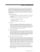
12. On systems not running HP XC, use the following procedure: a. Determine whether your system is a full bandwidth or reduced bandwidth configuration. If the cluster has a reduced bandwidth configuration, follow the additional test rules defined in Section 12.11. b. Run the qsnet2_dmatest on the appropriate nodes, depending on the cluster bandwidth. Specify the U1, U2, U3, U4, and U5 level arguments as explained in Section 12.4. Verify that all specified nodes pass on all levels. 13.
Figure 9-1: Diagnostic Flowchart Start Verify the configuration of the interconnects Interconnects are configured and pass the self test. No Configure or fix any problems Yes Verify all LEDs in the cluster with nodes powered on Run the qselantest on all nodes Did all nodes pass the qselantest? No Diagnose why the failing nodes are not able to communicate to the switch.
10 Using Component LEDs The LEDs in an interconnect network indicate the operational status of the network components. The following sections describe the location of the LEDs and how to check their status to confirm the operation of the network: • Finding the location of LEDs (see Section 10.1). • Using LEDs for component fault diagnosis (see Section 10.2). • Using LEDs for link fault diagnosis (see Section 10.3). 10.
Depending on the type of switch card installed in a slot, its port LEDs show the following status: • - The status of the link between the interconnect and the QM500 PCI card in the node - The status of the link between the node-level interconnect and the top-level interconnect in a federated cluster.
• - Fault – This is the over temperature LED which illuminates red if the PSU is too hot, perhaps because of a fan tray failure. Check the fan tray LEDs on the controller card. - Over Temp – This is the DC power good LED which illuminates green if the DC output is within acceptable limits or amber if the DC output is faulty. The QM580 clock generator box has the following status LEDs: - Pwr On, (power on) green. - Clk In OK, (clock in OK) green.
and the switch cards in the interconnect. A link can be node-to-interconnect, or interconnect-to-interconnect for federated configurations. The link LEDs are located on QM500 PCI cards in nodes, and on the switch cards in the interconnect. Each card has a group of three red, amber, and green LEDs. Each LED has the following meaning when illuminated: • Red – An error has been detected since the registers were last cleared. • Amber (flashing) – Data traffic flowing on the link.
10.2.2 Controller Card LEDs The LEDs on the interconnect’s QM503 control card provide the following diagnostic information: Label Color Interpretation Diagnostic Pri Clk OK green The input from the primary clock is good. This indicator applies only when the interconnect is part of a federated configuration. Error if OFF Sec Clk OK green The input from the secondary clock is good. Error if OFF B Clock Active amber The secondary controller (slot A) clock is inactive.
Master This clock is in master mode. Amber N/A (Status only) Error An error is detected in the clock generator box. OFF Red 10.3 Diagnosing Link Problems by Using the LEDs You can use the LEDs to diagnose the following links: • Preparing to run a diagnosis (see Section 10.3.1). • Diagnosing problems with the node level link (see Section 10.3.2). • Diagnosing problems with the top level link (see Section 10.3.3). 10.3.1 Preparing to run a Diagnosis Section 10.2.
_________________________ Note _________________________ Ignore illuminated red LEDs on connected links when the interconnect is first powered up. These will be cleared by the interconnect manager software. You can also Ignore red LEDs on unconnected links. If the green LED is lit at one end of the link cable but not the other, it is most likely that the LEDs are faulty; replace the appropriate component.
c. If the green LEDs are still not illuminated, proceed with step 11. 11. Test the node’s PCI I/O system, as described in the documentation supplied with the node. If the node’s PCI I/O system displays no errors, then the LED array is faulty and you must replace the appropriate components. You have completed the diagnostic process. 10.3.
be 650M/S, replace the clock distribution cables that are connected to each interconnect. c. Replace the link cable. d. Replace the switch card in the top-level interconnect. e. Replace the switch card in node-level interconnect. By the end of this procedure, you will have isolated and replaced the faulty component.
11 Accessing and Using the Interconnect Control Menu You manage single interconnects by making a connection to its controller card. For federated interconnects, the control network provides a mechanism for configuring and testing multiple interconnects. During HP Cluster Platform installation, the controller cards are linked via Cat-V Ethernet cabling to an HP ProCurve Ethernet switch.
Quadrics Switch Control Network Settings Name : QR0N00 MAC address : 004053072380 IP address : 172.20.66.1 Netmask : 255.255.255.0 Broadcast : 172.20.255.255 Protocol : STATIC TFTP Server : 194.202.174.19 Upgrade file : 503-upgrade.tar Gateway : 172.16.20.1 press return to return to menu: 11.2 Running the jtest Command Select option 3. Run jtest to invoke the jtest> prompt. You can run this utility either from the interconnect controller console or from the management server.
modules id .
• reset– Resets the JTAG interface • vpd – Show vital product data for selected boards, as recorded in the board level EEPROM. • state – Prints the state of the selected interconnect. • environment – Prints thermistor (environmental sensor) readings • verbose – Sets verbose mode 11.
• Each controller card is connected to the management network by an Ethernet cable. Before you can connect to the controller cards over the management network, you must assign an IP address to each controller card and ensure that it is configured for upgrades via TFTP protocol, as described in Section 9.3.2. • When you have assigned a IP address to a controller card, identify the current firmware version of the controller by using the jtest command, as described in Section 11.
7. To confirm that the upgrade has completed successfully, reconnect to the interconnect as follows: cp6000sms# telnet QR0T00 8. The Quadrics Switch Control menu is displayed again, as shown in step 1. 9. Choose option 3 to run the jtest command , as follows cp6000sms# jtest QR0T00 jtest: initialising module QR0T00 10.
12 Maintenance and Diagnostic Procedures The procedures described in this section enable you to diagnose and test your HP Cluster platform to resolve problems or as part of scheduled maintenance. The following procedures are described: • Using the interconnect firmware’s internal selftest utility, (see Section 12.1). • Using the qsnetstat script and manual procedures for environmental monitoring, (see Section 12.2). • Using the qselantest command to test links, (see Section 12.3).
• Polls the environmental sensors, determining fan speeds, PSU status, and component temperature. • Verifies and tests all the internal midplane connections between all installed and detected switch cards. • Verifies that the internal links between the detected cards are connected and fully operational. • Provides and option to review and reprint the results of either of its switch or midplane test stages.
- Possible Diagnoses: JTAG failure on the boards identified in the error message. 3 - Correction: Replace each board in turn, retesting each until the JTAG fault is rectified. Possible Diagnoses: Midplane fault associated with JTAG bus on the identified slots. 3 Correction: Replace the Midplane and re-test. ERROR cannot read lm75, suspected I2C failure on board X. • Location: Failure to read the temperature monitor on a specific (defined) board.
ERROR PSU X has missing Mains Input Good bit. ERROR PSU X has missing 48V DC Good bit. • Location: Main supply not within operational limits. - • Possible Diagnoses: See Table 12-1. Location: Output Voltage of PSU not within limits. - Possible Diagnoses: See Table 12-1. ERROR PSU X Fan Fail • Location: Specified PSU fan. - Possible Diagnoses: Fan obstruction. 3 Correction: Remove the obstruction from the specified power supply fan.
You can also select interconnects to test by specifying their name, as follows: cp6000sms# /usr/bin/qsnetstat QR0N00 QR0N01 The qsnetstat script checks the environment data on each interconnect. In federated interconnects, the qsnetstat script also verifies for each rail the consistency of the clock source and the software revision of the interconnects.
QR1T06 192.168.180.135 QS2_16X8 42-4022508 A/656 O/O OOOOOO 26’C QR1T07 192.168.180.136 QS2_16X8 42-4022508 A/656 O/O OOOOOO 27’C -Links In Reset -----------------------------------------------QR1N02 6:0:7 Held In Reset QR1N06 7:2:5 QR1N09 3:5:5 Held In Reset QR1N09 5:2:3 Held In Reset . . .
The remaining columns represent the error counts against the named link.
• Temperature: – The temperature for each sensor should be no higher than 40 degrees Celsius. • Fan speeds: – Fan speeds should be within a range of 2000 to 4400 rpm. • PSU status: – The power supply status should be on on (both PSUs healthy and supplying power). See Section 12.2.3 for information on verifying the clock status. 12.2.3 Verifying the Common Clock Source Normally, clock source B is a slave to clock source A, causing both generators to run at same frequency.
12.2.4 Verifying the View of the Network To ensure that there is a correct and consistent view of the interconnect network, you must verify the following: • That the QM500 PCI adapters in each node can see the correct network size. • Each node has the correct network position. To verify the network, look in the position file and obtain the following data values: • NodeId – The node identifier, in the format nNr0, where: n = Node N - An unique integer representing the node’s position in the network.
• PCI X connectivity. • Interconnect link interface. • PIO latency and bandwidth. • DMA latency and bandwidth. • Data consistency. The diagnostics software provides an initialization script named /etc/init.d/qspost that enables you to run qselantest as a service when a node boots. Configure the script by using the following command: # chkconfig -add qspost This command adds symbolic links in the /etc/rc.d/rc3.d, /etc/rc.d/rc4.d and /etc/rc.d/rc5.d. initialization files.
-h Displays the help (command usage) information. -x Exits automatically on encountering the first error. The default behavior is to ignore the error and continue. -s Exits with a status of 0 if all tests are passed, otherwise a status of 1. -D device_id Specifies a device identifier (rail) as 0, 1, or 0 1 (both). The default is 0 1 (both).
The following two examples show a successful run on a 16 port interconnect: # ./qsnet2_dmatest -a -e -se -dm -n10000 -RD 1m mnfr_dmatest: master self=0 peer=0 source 0x2000000000602000 dest 0x200000000460a000 event 0x2000000000703fe0 done 0x2000000004607fa8 mnfr_dmatest: using route’D’-> 00000000000000000000000000002008 0: reps 10000 min 1048576 max 1048576 inc 0 (batch 1) dma test will run for approx. 10 secs. please wait.. 0: 1048576 bytes 1145.02 uSec 915.77 MB/s # .
Each node owns a specific path through the network which it is responsible for testing. The path is derived from the node’s physical position in the network. You must first run a level1 test, followed by a level2 test and then a level3, up to the total number of levels present in the cluster topology. Any node that fails on level1 also fails during tests of subsequent levels because the node sends data through level1 to reach the higher levels.
• The -noparse option enables you to run the qsnet2_level_test utility so that it records the log files in the specified directory without parsing the log files (defers analysis of the logs). This option is useful during drain time testing where you have a limited time to perform preventative maintenance testing. After you return the cluster to production mode, you can use the -parse option to analyze the results.
• Verbose information is printed because -v is specified.
": ..." When communication is established with a interconnect module, basic configuration information is logged to syslog. ": swmserver restarted" This message indicates that communication with an interconnect module is established (such as after the swmserver process is restarted). ": heartbeat" Every five minutes, each interconnect module sends out this heartbeat message, indicating that it is functioning.
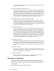
": clock: " This message indicates a change in the interconnect clock signal. A clock failure means the clock frequency has drifted +/-1.0 MHz from 656 MHz, while clock ok means the clock frequency has returned to within specification. 12.7.2 Using swmlogger for Production Mode Testing Use the output from the swmlogger to monitor the system during production mode, as described by the flowchart in Figure 12-1. Figure 12-1: Production mode Testing Using swmlogger Start.
since the last time that all the boards and chips were selected and cleared. When using this raw format of error data, you must decide whether the registers are reporting genuine link errors or simply errors due to node reboots. You look for a link to show errors repetitively, every day, during normal production mode testing. Use the following procedure to run this test: 1. Open a connection to the interconnect’s master control card, or launch the jtest utility remotely as described in Section 11.2. 2.
These errors are filtered out unless you use jtest with the verbose option. 12.9 Performing Drain Time Testing Unlike the production mode testing described in Section 12.7.2 and the log file monitoring described in Section 12.7, drain time testing does have an impact on cluster availability.
• qsnet2_level_test level2 • qsnet2_level_test level3 If the cluster is a federated configuration (more than 128 nodes), the qsnet2_drain_test script also runs the following tests: • /usr/bin/qsportmap. • qsnet2_level_test level4. _________________________ Note _________________________ Clusters might be configured with full bandwidth or reduced bandwidth, as defined in the configuration rules and cabling tables for your cluster.
xc4n15: tping -f gex 8k xc4n16: duplex ping complete xc4n16: tping -f gex 8k xc4n12: duplex ping complete xc4n12: tping -f gex 8k xc4n12: duplex ping complete xc4n12: tping -f gex 8k xc4n13: duplex ping complete xc4n13: tping -f gex 8k xc4n14: duplex ping complete xc4n14: tping -f gex 8k xc4n14: duplex ping complete xc4n14: tping -f gex 8k 0: 163840 bytes 1086.38 uSec 1: 163840 bytes 1086.38 uSec 2: 163840 bytes 1086.38 uSec 3: 163840 bytes 1086.39 uSec 4: 163840 bytes 1086.38 uSec 5: 163840 bytes 1086.
Table 12-2: Node ID Pattern for Testing Reduced Bandwidth Clusters (cont.) 0 – 4 Test this set of node IDs 5 – 7 Do not test 8 – 11 Test this set of node IDs 12 – 15 Do not test 16 – 19 Test this set of node IDs 20 – 23 Do not test Test and Verify the QM500 PCI Adapter in a Node 1. Verify the card’s LED status as described in Section 10.2. 2. Use the qselantest utility, as described in Section 12.3. Test and Verify the QM501 16-port Interconnect Card in a Node-level Interconnect 1.
c. Run the qsnet2_level_test level3 on all nodes connected to the interconnect, as described in Section 12.5. d. If configured as a federated solution, run the qsnet2_level_test level4 on all nodes connected to the interconnect, as described in Section 12.5. _____________________ Note _____________________ For systems not running HP XC, run the qsnet2_dmatest command on all nodes, as described in Section 12.4.
3. Run the qsnet2_level_test level1 on all 16 nodes connected to the card, as described in Section 12.5. 4. Run the qsnet2_level_test level2 on all 16 nodes connected to the card, as described in Section 12.5. 5. If there are less than 16 nodes connected to the card, run the qsportmap utility as described in Section 12.16. _________________________ Note _________________________ For systems not running HP XC, run the qsnet2_dmatest command on all nodes, as described in Section 12.4.
address if you replace a control processor card. The TCP/IP address for the new interconnect should remain the same. 12.12 Collecting QM500 Manufacturer Data (VPD) The manufacturing (VPD) data, such as its part number and serial number, for each QM500 PCI card is recorded in a file named vpd on each node. To obtain this data from a node, use the following procedure: 1. Change default to the data directory as follows: # cd /proc/qsnet/elan4/device0 2.
connectivity table. Database content is based upon the current interconnect module description or from command line arguments. You can also use this command to create a report on the network state compared to the database. The system impact is very low because the processes only manipulate database entries on one of the management nodes.
The following components are tested: • Fan tray • Power supply units • Temperature sensors • Clock source • Controller card firmware revision (in a federated network) The system impact is low: the test is a sequence of RPC calls to the switch managers running on the interconnects.
# qsportmap name Where name is an interconnect name, such as QR0T03. The command displays a table of boards and ports on the top-level interconnect. Each location shows the port on the node-level interconnect module to which a port on the top-level interconnect is connected.
13 Troubleshooting Nodes and Links The following techniques for troubleshooting are intended to assist you in identifying symptoms of common problems and to direct you towards appropriate diagnostics: • Node troubleshooting, (see Section 13.1). • Link cable troubleshooting, (see Section 13.2). 13.1 Troubleshooting Node Problems Node powers up but is otherwise dead or fails early in the BIOS It is possible that the QM500 network adapter is making a poor electrical connection in its PCI slot.
QM500 driver unable to determine network position The QM500 (Elan) driver reports that it is unable to determine network position The QM500 PCI adapter is found but the driver is unable to communicate with the network through the card. Proceed as follows: 1. Verify that the card is actually functioning using qsnelantest. It is possible that the driver is only able to communicate partially with the card. If qselantest fails, it is likely that the card is poorly seated in its PCI connector. Reseat the card.
2. Test the node using qselantest and qsnetcabletest to confirm whether the node is functional or not. 3. Test every other node in the segment by using qselantest and qsnetcabletest to verify their integrity. Using a tool such as pdsh with dshbak is helpful for sorting the diagnostic output. 13.2 Troubleshooting Link Problems A high occurrence of network errors seen using the qsnetstat or qsneterr diagnostics Network errors are often due to a badly seated or failing link component.
b. On the second occurrence of an error at the same link location, repeat the procedure described in Step a. c. On the third occurrence of an error at the same location, replace the cable. d. On the first occurrence of an error in the same location with the new cable, replace one of the switch cards to which the cable is connected. If the errors are cleared then the replaced switch card is at fault. If the error persists then replace the other switch card.
A Components Required The tables in this appendix specify the quantities of components that are required to build a cluster, depending on the number of nodes and the bandwidth. Each table is preceded by a parts count for the parts quantities that do not vary. The table headings provide the following information: • IC – Interconnect, meaning the enclosure or chassis. • Bounded IC – The number of bounded interconnect enclosures required.
Bounded Cluster to 128 Nodes, Reduced Bandwidth The following parts list specifies parts that are the same for all node counts: Part Quantity Bounded interconnect enclosure (chassis) 1 The following table specifies the additional parts and count required, depending number of nodes in the cluster: Table A-1: Bounded Cluster to 128 Nodes, Reduced Bandwidth Number of Nodes QM511C Cards QM511L Cards Link Cables 0-16 1 7 = nodes 17-32 2 6 = nodes 33-48 3 5 = nodes 49-64 4 4 = nodes 65-80
Federated Clusters of 129-256 Nodes, Reduced Bandwidth The following parts list specifies the parts that are the same for all node counts: Part Quantity Top level interconnect enclosure (uses a transpose midplane that has no link connectors).
Federated Clusters of 257 to 512 Nodes, Reduced Bandwidth The following parts list specifies the parts that are the same for all node counts: Part Quantity Top level interconnect enclosure (uses a transpose midplane that has no link connectors).
Federated Clusters of 257 to 512 Nodes, Full Bandwidth The following parts list specifies the parts that are the same for all node counts: Part Quantity Top level interconnect enclosure (uses a transpose midplane that has no link connectors).
Federated Clusters of 513-1024 Nodes, Reduced Bandwidth The following parts list specifies the parts that are the same for all node counts: Part Quantity Top level interconnect enclosure (uses a transpose midplane that has no link connectors).
Federated Clusters of 513-1024 Nodes, Full Bandwidth The following parts list specifies the parts that are the same for all node counts: Part Quantity Top level interconnect enclosure (uses a transpose midplane that has no link connectors).
B Quadrics QsNet Interconnect FRU Components II The field replaceable units for the QsNetII interconnect are defined in Table B-1. Table B-1: Quadrics QsNetII FRU Components Description Kit 6-3 No. QM500 PCI-X adapter rev B AB992A 356716-001 3X-CM500-BA 2-5-2 Part No.
C Component Specifications This appendix provides operating and performance specifications for cluster components. Specifications might change for individual components as products are improved. Consult the user information for a specific components to obtain the latest specification and operation restrictions. C.1 Quadrics® QsNetII™ Model QS64A 128-port Interconnect The following table presents the operating and performance specifications for the QsNetII interconnect.
Operating and Performance Specifications Idle or Operating LWAd, bels LpAm, dBA 7.2 B 56 dBA C.2 Quadrics® QsNetII™ Model QS32A 16-port or 32-port Interconnect The following table presents the operating and performance specifications for the QsNetII interconnect. Operating and Performance Specifications Height 17.5 cm (4U) 6.8 in Depth 48 cm 18.7 in Width 44 cm 17.2 in Weight 16 kg 35.
• The dimensions of the QM500 are as follows: • Length 178 mm Width 125 mm • Depth 22 mm Weight 0.13 Kg • The dimensions of container in which the QM500 is shipped are as follows: • Length 300 mm Width 125 mm • Depth 25 mm Weight 0.25 Kg • Environmental Characteristics • The maximum ambient room temperature at which the QM500 can operate is 35 • degrees Celsius (95 degrees Fahrenheit).
Physical Specifications C-4 Storage temperature Not tested Operating humidity 20 C to 80 C Storage humidity 10 C to 90 C Maximum operating altitude 3037 m (10,000 ft) Maximum shipping altitude 12190 m (40,000 ft) Operating vibration 10 – 500 Hz Operating shock 7.
D Output From the qselantest Utility Using the qselantest utility is described in Section 12.3. The output from the test is extensive and is broken down for description as follows: • Device information (dev_info) is described in Section D.1. • PCI Bus information is described in Section D.2. • Thread processor information is described in Section D.3. • SDRAM memory information is described in Section D.
MV: MS: DT: DV: DS: DG: DD: 1.00 00000000 00 00 00 00 00 Replace the QM500 PCI adapter under the following circumstances: • An uncorrectable error occurs. • The driver reports multiple errors. • A high rate of correctable errors occur on the same QM500 network adapter in a short period of time. D.1 Device Information qselantest: testing device(s) 0 Device 0: -----------------------------------------------------------qsnet2_regtest dev_info 14fc 1 0 ...
Show_pci: reading data...
tmemtest: allocated main condition vars tmemtest: thread init tmemtest: waiting for thread tests to start...
Addrs: 200000000061a6a0 - 2000000000632d38 qselantest Output -----------------------------------------------------------------------qsnet2_probe ...STARTED ----------------------------------------------------------------------Mode Switched NodeId 0 NumLevels 2 NumNodes 16 qsnet2_probe ...PASSED ----------------------------------------------------------------------qsnet2_dmatest -e -RM -se -dm -n 1000000 -S 0 ...
Addrs: 200000000460a000 - 2000000004622698 mnfr_dmatest: Pattern: ffffffffffffffff words: 12500 Addrs: 20000000046226a0 - 200000000463ad38 mnfr_dmatest: Pattern: 5555555555555555 words: 12500 Addrs: 200000000463ad40 - 20000000046533d8 mnfr_dmatest: Pattern: aaaaaaaaaaaaaaaa words: 12500 Addrs: 20000000046533e0 - 200000000466ba78 mnfr_dmatest: Pattern: 00ff00ffff00ff00 words: 12500 Addrs: 200000000466ba80 - 2000000004684118 mnfr_dmatest: Pattern: 00ff00ff00ff00ff words: 12500 Addrs: 2000000004684120 - 200000
E Preventing Electrostatic Damage To prevent damaging the system, you must follow the configuration procedures and be aware of the standard precautions for handling electronic parts. A discharge of static electricity from a finger or other conductor may damage system boards or other static-sensitive devices. This type of damage can reduce the life expectancy of the device. E.
F Cable Types This appendix explains the types of cables used in the interconnect , and illustrates the default wiring topology for standalone and federated networks. There are four types of interconnect cables: JTAG The JTAG cable connects the parallel port on the switch-managing node to the JTAG port on the interconnect. The JTAG cable is a 1-m IEEE1284 parallel-port cable. Link A link cable connects each node to the interconnect.
Index Numbers and Special Characters 16/32-port interconnect, 4-1f battery, 8-10 cable management, 8-2 cabling, 4-2 characteristics, 4-2 compact flash memory, 8-10 controller LEDs, 4-5 controller module, 8-8 controller ports, 4-5 fan module, 4-2, 8-7 LEDs, 4-2 physical features, 4-1 ports, 4-1 power, 4-1 reset, 4-2 status LEDs, 4-4, 4-5 switch card, 8-8 A AC Good LED, 10-2 address, IP, 2-5 B B Clock active LED, 10-2 B Cntrl Active LED, 10-2 bandwidth, 1-5 bisectional, 2-2 battery, replacing, 8-10 BIOS, 11
verifying, 6-3, 12-8 cluster bandwidth, 1-5 bounded, 1-5, 3-4 connecting components, 1-3 dense, 1-5 federated, 1-6, 3-5 node count, 1-5 platform packaging, 1-5 terminology specific to, 1-1 topology, 1-6 Cntrl Error LED, 10-2 collecting QM500 data, 12-25 command jtest, 11-1, 11-2, 12-7 qsctrl, 12-26 qsdiagadm, 12-25 qselantest, 12-10, 12-11 qselantestp, 12-11 qsnet2_dmatest, 12-11 qsnet2_level_test, 12-12 qsnet2soaktest, 12-15 qsnetsoak, 12-25, 12-28 qsnetstat, 6-3, 12-4 qsportmap, 12-27 selftest, 12-1 compa
E elan, 2-1 electrostatic discharge overview, E-1 prevention measures, E-1 elite, 2-1, 2-2, 2-3, 3-1 EMI, 5-2, 7-16 environmental monitoring, 12-4 error link, 12-17 PSU messages, 12-4 selftest messages, 12-2 Error LED (QM580), 10-3 ESD grounding, E-1 preventing, E-1 Ethernet cable, 2-2, 4-4 Ethernet port LED (QM503), 10-2 events, 12-15 external clock source, 7-12 F fan, 3-3 16/32-port interconnect, 4-2 installing tray, 7-10 replacing module, 8-7 Fan Fail A LED, 10-2 Fan Fail B LED, 10-2 fat tree topology,
environmental monitoring, 12-4 error messages, 12-2 fan module, 3-3 installing, 7-1 maintenance, 7-1, 12-1 midplane, 2-2 mode, 11-1 modules, 7-1 name, 2-4 network components, 2-1 network settings, 11-1 port LEDs, 10-4 postinstallation verification, 9-1 power module, 3-3 power up, 7-11 rebooting, 11-1 replacing midplane, 7-16 security, 11-4 self test, 11-4 selftest command, 12-1 show configuration, 11-2 slot numbers, 3-4 testing, 11-1 upgrading firmware, 11-4 variations, 3-4 verify network, 12-9 verifying wi
soak test, 12-25 testing modules, 12-21 testing QM500, 12-22 testing QM501, 12-22 testing QM502, 12-22 testing QM503, 12-24 testing QM511C, 12-23 testing QM511CL, 12-24 managing cables, 1-4 mapping ports, 12-27 Master LED (QM580), 10-3 message passing interface, 2-1 messages logged, 12-15 midplane, 2-2, 3-2 QM540, 2-3 QM542, 2-3 replacing, 7-16 mode, 11-1 controller card, 9-4 module, 7-1 16/32-port interconnect, 8-8 fan, 3-3 hot swap, 7-6 power, 3-3 testing, 12-21 MPI, 2-1 N network, 2-2 cable guidelines,
PSU error messages, 12-4 query controller using qsctrl, 12-26 self test, 12-1 self test error messages, 12-2 soak test, 12-25 soak testing, 12-28 testing modules, 12-21 testing QM500, 12-22 testing QM501, 12-22 testing QM502, 12-22 testing QM503, 12-24 testing QM511C, 12-23 testing QM511CL, 12-24 verify clock source, 12-8 verify interconnect, 12-4 verify network, 12-9 verify node position, 12-9 verify QM500, 12-9 procedure for cabling, 1-5 production mode testing, 12-17 PSU, 12-4 ( See also power ) error m
S security interconnect, 11-1, 11-4 self test error messages, 12-2 interconnect, 11-4 procedure, 11-1 selftest command, 12-1 settings network, 11-1 show network settings, 11-1 site preparation preventing electrostatic damage, E-1 Site Preparation Guide, 1-6 slot numbers, 3-4 soak test, 12-15, 12-25 qsnetsoak, 12-28 software rebooting, 11-1 upgrade, 11-4 specifications, C-1 static electricity, E-1 static-dissipating work mat, E-1 static-sensitive devices, E-1 status monitoring, 12-4 storage, 1-7 straps heel,
query controller using qsctrl, 12-26 selftest command, 12-1 selftest error messages, 12-2 soak test, 12-25 soak testing, 12-15 testing level with qsnet2_level_test, 12-12 using LEDs, 10-3 verify interconnect, 12-4 two-stage network, 2-2 U user interface Index-8 accessing, 11-1 V verifying clock source, 6-3, 12-8 verifying links, 7-15 VGA port, 7-12 video monitor, 1-7 W wrist strap, E-1