
Quadrics QsNetII Interconnect
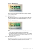
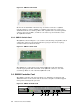
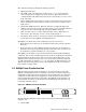
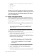

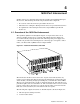
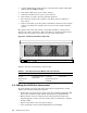
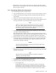

Figure 3-6: QM511C Switch Card
Each of the 16 downlinks of the first stage of switches connects to a QM500
network adapter. 2 of the 4 uplinks of each Elite in the first stage connect to 8
downlinks from the 2 second stage Elites. The 8 uplinks of the second stage Elites
connect to the top level Elite, one link to each of the 8 top level switches across
all 8 QM511C modules.
3.3.4 QM511L Switch Card
The QM511L, shown in Figure 3-7, is a switch card containing a single Elite switch
components. It has no ports and provides the top stage in the fat tree topology
of clusters with fewer than 128 nodes.
Figure 3-7: QM511L Switch Card
The QM511L is a replacement for the omitted QM511C cards and completes
network topology Each link of the Elite on the QM511L connects to one of the
second stage Elites on each of the fitted QM511C cards.
3.4 QM503 Controller Card
The QM503 controller card, shown in Figure 3-8, distributes clock signals and
JTAG information to the switch cards. It also hosts a daughter card that supports
management and diagnostic processes.
Figure 3-8: QM503 Controller Card
Sec Clk Ok
B Clk Active
Clk Error
Federated
Redundant
Ctrl run
Ctrl Error
B Ctrl Active
Fan Fail A
Fan Fail B
Reset
Shutdown
COM 1
Mouse
Kybd
10/100
BASE-T
VGA
Pri Clk
Sec Clk
QM503
QUADRICS
Pri Clk Ok
X
Y
[
Z
\
]
Fan B / Ctrl B
3-8 128-Port Interconnect Modules