
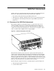
Quadrics QsNetII Interconnect


the correct power outlet ensures that the rack’s power draw is balanced
across the power distribution units.
Connect the power cable to the IEC60320 appliance inlet on the 16/32-port
interconnect. When powered up, normal operation of the fan and PSU
Module is indicated by the illumination of the green LED labeled Power.
b. Controller Ethernet cable.
c. Terminal and keyboard, if you plan to perform local configuration tasks.
Clock cable connections are not used in HP Cluster Platform configurations
because the 16/32-port interconnect is not supported for federated
configurations and therefore timing signal synchronization is not required.
4.2.2 Disconnecting and Removing the Interconnect from the Rack
Use the following procedure to disconnect cables (such as for replacement) or to
remove the chassis from the rack:
1. Ensure that you know the node origin and the port destination of each cable
for all ports on the interconnect (including Ethernet). If the ports are not
already labeled so that you can reconnect them without error, make labels for
each cable before you disconnect a cable.
2. Bring the cluster or an individual node to an appropriate state for the task.
You can replace an one or more link cables without shutting down the cluster
providing that you quiesce traffic on the link or shut down the node.
3. Disconnect the cables in the following order:
a. Loosen or open the cable management upper retainer and disconnect the
link cables. If you are replacing a cable only, remove the failed link cable
and insert and connect the new cable. If removing the chassis, proceed
with the following steps.
b. Disconnect the power-supply cable.
c. Disconnect the clock cable, if included in your cluster configuration.
d. Disconnect the controller Ethernet cable.
e. Disconnect the terminal and keyboard, if connected.
4. Remove the four locking screws that secure the slides to the front rack
columns. Pull on the chassis handles to slide out the chassis about 6 inches.
_______________________ Note _______________________
If the chassis is difficult to move, slightly loosen the screws
holding the tracks to the rack to allow for some play in the track
components. Remember to secure these screws afterwards.
_____________________ Caution ______________________
The next step requires two people to lift the chassis out of the rack
5. Slide the chassis all the way out of the rack and place it on a level, stable
work surface.
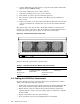
4.3 Understanding the Signal LEDs
Each link port has a group of three signal LEDs that provide status information
listed in
4-4 16/32-Port Interconnect