
Quadrics QsNetII Interconnect


Color
Interpre-
tation
Normal Status Alternate Status
Green Link
function
Illuminated if the link is
functioning.
Unlit if the link has a problem
or is disconnected.
Yellow Link
activity
Illuminated or flashing if data
traffic is passing through the link.
Unlit if no data is passing
through the link.
Red Link error Off. On – there is an error on the link.
a
a
The red LED illuminates after you connect a link to a node because the link resets when the node boots. The
LED will go off after the node has booted.
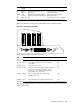
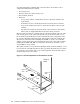
Figure 4-3 shows the location of the signal LEDs on the controller module.
Figure 4-3: Controller Signal LEDs
Pri Clk
Sec Clk
Clk Err
VGA KYBD
10/100
BASE T
CLKA/CLKB COM 1 RESET
Pwr On
Ctrl Run
Ctrl Err
31
30 29 28
These LEDs provide the following information:
LED
Color
Interpretation
Error Status
Pri Clk Green Primary clock input is good. (Federated mode only). Off
Sec Clk Green Secondary clock input is good. (Federated
mode only).
Off
Clk Err Red Clock error is detected. On
Pwr On Green Switch is powered on. When power is applied,
the cooling fans must be running. If you
do not see or hear the fans, switch off the
interconnect. See Section 8.2.
Off
Ctrl Run Green The controller CPU has booted and is
running normally.
a
Off
Ctrl Err Red The controller CPU watchdog has timed out On
a
After cycling the power or resetting the controller, you must allow five minutes for the Ctrl Run LED to illuminate.
The function of the ports on the controller card is identical to that of the 128–port
interconnect chassis.
16/32-Port Interconnect 4-5