
Quadrics QsNetII Interconnect


5
QM500 Network Adapter
This chapter provides a generic installation procedure for the QM500 network
adapter in a node and how to service the QM500. It should be read in conjunction
with the instructions supplied with the node computer for fitting a PCI X card. See
the
Servers and Workstations Guide for specific instructions for certain models of
HP servers. The successful conclusion of the installation process results in the
illumination of the green LED on the QM500 network adapter. This indicates that
the link’s physical communication layer is operating correctly.
5.1 Selecting a PCI Slot
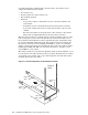
The QM500 is a Universal, short, 64-bit PCI card that conforms to PCI X
specification 1.0. (See Figure 3-1). To obtain the maximum communications
bandwidth in HP Cluster Platform, it must be installed in a PCI X slot that
supports a clock speed of 133 MHz, a 64-bit wide bus and a 3.3 V DC power supply.
The card operates from a 3.3 V DC power supply and consumes less than 10 W. The
choice of slot to use depends on the server model in which the adapter is installed.
The QM500 makes very heavy use of the PCI or PCI X bus. Inter-node
communication performance will be significantly reduced if the PCI or PCI X bus is
servicing other devices. Install the QM500 in the specified server slot only. Do not
install other PCI devices that will share a PCI or PCI X bus with the QM500.
________________________ Caution _______________________
When installing the QM500, take care to follow procedures for
preventing electrostatic damage.
Specific PCI slot locations are defined in the Servers Guide.
5.2 Installing and Removing the QM500 Network Adapter
The following procedures are generic instructions for PCI card installation. Consult
the Workstations and Servers Guide for specific instructions for HP server models.
5.2.1 Installing the QM500 Network Adapter
The procedure for installation of the QM500 is as follows:
1. Halt the system (if booted) and power it down.
2. Place the QM500 and any other static-sensitive components being installed
on the antistatic mat.
3. Remove the appropriate side panel.
4. Remove the PCI filler panel from the selected slot.
5. Hold the QM500 by its edges and push it into the slot. system.
6. Tighten the screw which fastens the faceplate of the QM500 to the rear panel
of the system.
7. Replace the side panel.
QM500 Network Adapter 5-1