
Quadrics QsNetII Interconnect
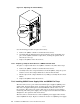


6. The tray can move freely on the slides. Slide it all the way to the rear of the
rack.
_______________________ Note _______________________
The tray might move as you are lifting in the interconnect
enclosure. Hold the tray as you slide the enclosure forward.
7. Remove the protective covers and the nuts and washers from the two threaded
studs at the base of the interconnect enclosure. Retain these fasteners for
later use.
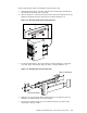
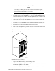
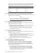
8. Using two people to lift the enclosure, lift it on to the tray and push it forward
until the two studs at the base of the interconnect enclosure protrude through
the tabs on the tray, as shown in Figure 7-4.
_______________________ Note _______________________
Slots 4 through 7 are oriented toward the front of the rack, while
slots 0–3 are at the rear of the rack. See Figure 3-3.
Figure 7-4: Mounting the Enclosure on the Rail Kit
Rear of the Rack
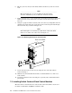
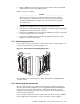
9. Secure the interconnect to the tray by using the two nuts and washers
removed in Step 7.
10. Slide the tray forward until the brackets are flush with the face of the rear
rack columns
11. Secure the brackets to the rack using six cage nuts, bolts, and washers (three
per bracket).
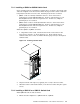
7.3 Installing Switch Card and Clock Control Modules
The interconnect enclosure has five vertical slots at the front and five at the rear
for switch card modules and QM503 controller cards.
7-4 Installation and Maintenance of the 128-Port Interconnect