
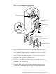
Quadrics QsNetII Interconnect

2. Verify that the Main menu is displayed, pressing Return to redraw the screen
as necessary.
3. Select menu option Set Module Mode by pressing 4 followed by Return.
4. In response to the prompt Set Federated "y" or "n", press y for a federated
switch or n for a standalone Switch, followed by Return.
5. In response to the prompt Set Redundant "y" or "n", press y if a second QM503
is, or will be, installed in slot Ctrl B, otherwise press n followed by Return.
6. After several seconds the Main menu should be displayed again.
7. Cycle the power on the interconnect by turning off the power (on both QM561
power supply units if fitted) for several seconds, then turning the power back
on again.
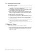
7.5 Checking the QM503 Controller Card LED
The QM503 controller card has a set of LEDs that indicate the status of the
interconnect. Check the LEDs to verify the correct installation of the QM503s and
the QM584 clock cables. Table 7-2 shows the meaning of the LEDs. Note that
where QM503s are installed in both slots Ctrl A and Ctrl B to provide redundancy,
the LED status should be the same for both QM503s. If an LED indicates an error
status, refer to the diagnostics section.
Table 7-2: QM503 controller card LEDs
LED Color Meaning when Lit Error Status
Pri Clk Ok Green Primary clock input good (Federated mode only). Off
Sec Clk Ok Green Secondary clock input good (Federated mode only). Off
B Clock
Active
Yellow Secondary QM503, slot A, clock inactive On
Clk Error Red Clock error On
Federated Green Federated mode configured
Redundant Green Redundant mode configured
Ctrl Run Green QM503 booted and running normally (Allow 5
minutes after cycling the power or resetting the
QM503 for the Ctrl Run LED to illuminate).
Off
Ctrl Error Red QM503 in slot A is not operational Off
B Ctrl
Active
Yellow QM503 in slot B is not operational Off
Fan Fail A Red QM562 in Fan Tray A is not operational On
Fan Fail B Red QM562 in Fan Tray B is not operational ON
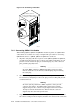
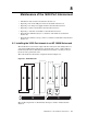
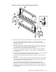
7.6 Connecting Link Cables
Each QM501, QM502 and QM511C has connections for up to sixteen link cables
(the QM511L has no connections). In HP Cluster Platform, the link cables are
labeled according to their origin and destination ports in nodes or in other
interconnects. The cabling tables that define the wiring solutions for clusters of
different sizes. Figure 7-10 shows how to correctly connect link cables.
Installation and Maintenance of the 128-Port Interconnect 7-13