
Quadrics QsNetII Interconnect
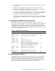
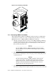
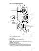
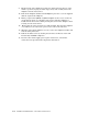
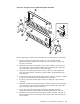
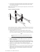

Figure 7-10: Connecting Link Cables
Ensure that the connector
fits the socket within a tolerance
of 10 degrees of the horizontal
PSU A
PSU B
QU
a
D
rics
QsNet"
QsNet"
HPTC-0029
Cable
Connector
Socket
Cover
10
10
7.6.1 Connecting QM581 Link Cables
When linking QM501, QM502 and QM511C modules together, use QM581 link
cables which are available in a range of lengths. The procedure for connecting
QM581 link cables to a QM501, QM502 or QM511C is as follows:
1. Align the cable plug with the receptacle on the QM501, QM502 or QM511C,
carefully insert the plug into the receptacle and, while maintaining an even
pressure on both ends of the plug to avoid damaging any of the connector
pins, push the plug fully home.
_____________________ Warning _____________________
To ensure EMC compliance, EMC Spring Finger Connector Clips
must be attached to each connector, with all spring fingers touching
the cable plug.
2. When the cable plug is fully inserted, push the locking tab in fully and check
for retention by attempting to remove the plug. Correct locking will prevent
accidental removal.
_____________________ Warning _____________________
To ensure system performance, EMC compliance and to prevent
connector clip damage, the QM581 link cable must be suitably
supported to prevent a connector angle displacement of more than
10 degrees from the horizontal line. Ensure that the cables are
supported by the cable management bars.
3. Support the cable using available cable management systems to ensure that
the connector and port remain aligned, and there is no stress on the connection.
7-14 Installation and Maintenance of the 128-Port Interconnect