
Quadrics QsNetII Interconnect

10
Using Component LEDs
The LEDs in an interconnect network indicate the operational status of the
network components. The following sections describe the location of the LEDs and
how to check their status to confirm the operation of the network:
• Finding the location of LEDs (see Section 10.1).
• Using LEDs for component fault diagnosis (see Section 10.2).
• Using LEDs for link fault diagnosis (see Section 10.3).
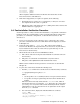
10.1 Locating the Diagnostic LEDs
The components in a link each have the following LEDs (light emitting diodes):
• There is a stack of LEDs on the QM500 network adapter in each node. The
stack contains three LEDs, arranged from left to right in the following order:
red, yellow, green. The LEDs on the QM500 network adapters, together with
the LEDs on the interconnect switch cards, Indicate the status of the links
between the cluster nodes and the interconnect.
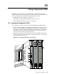
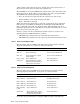
• The switch cards located in the interconnect have three LEDs of red, amber,
and green color adjacent to each switch card port (16 per card). An example is
shown in Figure 10-1, callout 8.
Figure 10-1: Interconnect Modules – Front Panels
Sec Clk Ok
B Clk Active
Clk Error
Federated
Redundant
Ctrl run
Ctrl Error
B Ctrl Active
Fan Fail A
Fan Fail B
Reset
Shutdown
COM 1
Mouse
Kybd
10/100
BASE-T
VGA
Pri Clk
Sec Clk
QM502-C
QUADRICS
QM564
QUADRICS
QM503
QUADRICS
Pri Clk Ok
`
X
Y
[
^
Z
_
\
]
Slot 5 Slot 4Fan B / Ctrl B
2
3
4
5
Using Component LEDs 10-1