
Quadrics QsNetII Interconnect

Depending on the type of switch card installed in a slot, its port LEDs show
the following status:
- The status of the link between the interconnect and the QM500 PCI card
in the node
- The status of the link between the node-level interconnect and the top-level
interconnect in a federated cluster.
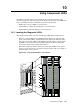
• The QM503 controller card has the following status LEDs as shown in
Figure 10-1, callout 1:
- Pri Clk OK (green)
- Sec Clk OK (green)
- B Clock active, (amber)
- Clk Error, (red)
- Federated, (green)
- Redundant, (green)
- Ctrl Run, (green)
- Cntrl Error, (red)
- B Cntrl Active, (amber)
- Fan Fail A, (red)
- Fan Fail B, (red)
- Ethernet (network) port, amber and green (green indicates a good
connection, amber flashes to indicate that data traffic is flowing), See
Figure 10-1, callout 3 for the location of this port.
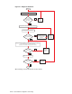
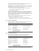
With the exception of the network port, the controller LED labels are illustrated
in Figure 10-2.
Figure 10-2: QM503 Timing and Control Card LEDs
• The QS5A power supply has the following status LEDs, which are all red:
- AC (alternating current in) Good – This the AC power good LED which
illuminates green if the AC inlet supply is working or red if the supply is
faulty.
- DC (direct current out) Good – This LED illuminates red if the AC inlet
supply or the DC output is not within acceptable limits.
10-2 Using Component LEDs