
Quadrics QsNetII Interconnect
- Fault – This is the over temperature LED which illuminates red if the
PSU is too hot, perhaps because of a fan tray failure. Check the fan tray
LEDs on the controller card.
- Over Temp – This is the DC power good LED which illuminates green if the
DC output is within acceptable limits or amber if the DC output is faulty.
• The QM580 clock generator box has the following status LEDs:
- Pwr On, (power on) green.
- Clk In OK, (clock in OK) green.
- Master, amber – This LED indicates that the clock box is the master source
of the signal for the network.
- Error, red.
10.2 Using the Component LEDs for Fault Diagnosis
The component LEDs provide a first level diagnostic for hardware problems. The
following sections explain how to use the LEDs to isolate hardware faults or to
determine the proper operation of hardware and thus isolate a potential software
problem.
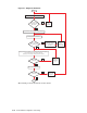
Link LEDs are those that enable you to verify the status of a cable connection
between one component and another, such as the QM500 PCI card in a node
and the switch cards in the interconnect. A link can be node-to-interconnect, or
interconnect-to-interconnect for federated configurations. Each card has a group of
three red, amber, and green LEDs. Each LED has the following meaning when
illuminated:
• Red – An illuminated red LED has three possible interpretations
- An error has been detected since the registers were last cleared.
- The module is initializing or the node is rebooting and the LED will stop
glowing when the process is complete (indicating a good link).
- There is no link cable installed (unused port).
• Amber (flashing) – Data traffic is flowing on the link.
• Green – The link is connected and good.
Where two functional components are powered on and connected by a functional
link cable, the green LEDs are illuminated. An illuminated red LED indicates
that a component or the link cable might be faulty. The fault might only be an
installation problem, such as a card that is not correctly seated in the slot or a
cable that is not securely seated in a port. You can use the LEDs to diagnose the
network as follows:
• Using LEDs to diagnose problems in the link between a node and its port on
the interconnect is described in Section 10.2.1.
• Using LEDs to diagnose problems in the interconnect controller card is
described in Section 10.2.2.
• Using LEDs to diagnose problems in the power supply unit (PSU) is described
in Section 10.2.3.
• Using LEDs to diagnose problems in the clock generator is described in
Section 10.2.4.
10.2.1 Link LEDs
Link LEDs are those that enable you to verify the status of a cable connection
between one component and another, such as the QM500 PCI card in a node
Using Component LEDs 10-3