
HP Cluster Platform Core Components Overview


2.6.1 HP ProCurve 2610-48 and 2610-24 Switch Overview
The HP ProCurve Switch 2610 Series includes the 24-port HP ProCurve Switch 2610-24 with 24
10/100Base-TX ports, and the 48-port HP ProCurve Switch 2610-48 Switch with 48 10/100Base-TX
ports. There are three other models in the ProCurve Switch 2610 Series, the 2610-PWR models,
which are not discussed in this document.
The features of the HP ProCurve 2610-24 and 2610-48 switches include:
• Twenty-four 10/100 ports (HP ProCurve 2610-24) or forty-eight 10/100 ports (HP ProCurve
2610-48)
• 10/100 auto-sensing per port, which automatically detects and sets the speed for any 10base-T
or 100 Base-TX device
• Auto-MDIX, which automatically adjusts for straight-through or crossover cables on all
10/100 ports
• Two mini-GBIC slots for gigabit uplink connectivity
• Two 10/100/1000Base-T ports for gigabit uplink connectivity
• LED displays with per-port indicators
• Automatic polarity correction and autopartitioning on all ports
• Built-in bridge that automatically connects 10 Mb/s and 100 Mb/s devices
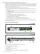
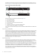
The major difference between the ProCurve 2610-24 and 2610-48 switches is in the number of
ports, as shown in Figure 2-8.
Figure 2-8 HP ProCurve 2610-48 Switch
Mode
All RJ-45 ports (1 - 26 ) ar e Auto - MD IX
Mode
Mode
Link
Link M ode
*
Reset
Clear Spd Mode
Off = 10 Mbps, Off = 10 Mbps,
Link M ode
-
G ig -T Po rts SF P Po rts
Link
Link
Base-TX Ports (1- 12) 10 /100Base
-
TX Ports 13 -24 )
26
2319
*
R P S
Act
FDx
Spd
Test
Procurve
Power
Fault
Locator
Console
switch 2610 -24
J9085A
Status
LED
Module
2 2
2 1
2 4
2 3
2 01 8
1 6
1 4
1 91 7
1 5
1 3
1 2
1 0
8
6
1 1
9
7
5
4
2
31
Networking by HP
27 28
1
8
2 4
6
3
7
7
11
9
5
10
Procurve
Power
Fault
Locator
Console
2 2
2 1
2 4
2 3
2 01 8
1 6
1 4
1 91 7
1 5
1 3
1 2
1 0
8
6
1 1
9
7
5
4
2
31
ModeLinkMode ModeLink
ModeLink
Link
Link Link
Mode
Mode Mode
Mode
Link
Link
Link Link
Link Mode
Use only ProCurve mini-G BICs and SFPs
G ig -T Po rts SF P Po rts
4 9
3 7
3 8
3 63 43 23 0
3 53 33 12 9
2 82 6
2 7
2 5
4 6
4 5
4 8
4 7
4 44 24 0
4 34 13 9
5 0
5 25 1
A ll R J-45 ports (1 - 50) are A uto-M D IX
*
4
5
6
7 8
Act
FDx
Spd
Test
Test
Test
LED
Module
Status
1
2
7
11
9
10
3
The following items correspond to the callouts in Figure 2-8:
1. Power, Fault, and Locator LEDs.
2. Console port
3. RPS, Fan, and Test status LEDs
4. Reset button
5. LED Mode selection button and indicator LEDs (Act, FDx, Spd)
34 Platform Core Components