
HP Cluster Platform Core Components Overview
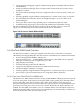
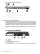
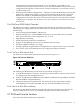
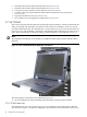
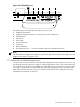
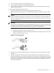
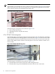

Figure 2-13 HP ProCurve Switch 2848 Front View
Power
Fault
Dual Personality Ports 10/100/1000-t(T) or Mini-GBIC(M)
off = 10Mbps flash = 100Mbps on = 1000MbpsSpd Mode
hp P roCurve
Switch 2848
J4904A
Use only one (T or M) for each port
M
T
M
T
M
T
M
48474645
T
1
2
3
4
5
6
7
8
9
10
11
12
13
14
15
16
17
18
19
20
21
22
23
24
25
26
27
28
29
30
31
32
33
34
35
36
37
38
39
40
41
42
43
44
Reset Clear
Fan
Test
RPS Act
FDx
Spd
Lnk
Status
LED
Mode
4
1
2
3 5
6
7
1. Power and Fault LEDs
2. Reset and Clear buttons
3. Test and Fan status LEDs
4. Port LED view select button and indicator LEDs
5. Switch port LEDs
6. 10/100Base-TX RJ-45 ports
7. Dual-personality ports (1000Base-T or mini-GBIC)
2.6.4.2 Rear View of the ProCurve 2848 Switch
The HP ProCurve 2848 switch has a power connector, but it does not have a power switch. It is
powered on when connected to an active AC power source. The switch automatically adjusts to
any voltage between 100 volts and 240 volts (50–60 Hz). No voltage range settings are required.
When the switch is powered on, it performs a diagnostic self-test that takes about 50 seconds to
complete.
The console port on the back of the ProCurve 2848 switch (Figure 2-14 “HP ProCurve Switch
2848 Rear View”) connects the switch to a console via a serial cable. The console can be a PC or
a workstation running a VT-100 terminal emulator. The RPS slot allows you to connect the
ProCurve 2848 to a redundant power supply unit (optional).
Figure 2-14 HP ProCurve Switch 2848 Rear View
1 2 3 4
1. Console port
2. Cooling vents
3. Redundant Power Supply (RPS) input
4. AC power connector
The rear panel also has cooling vents, which must not be obstructed for proper switch operation.
42 Platform Core Components