
HP Cluster Platform Core Components Overview
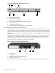
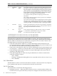
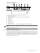
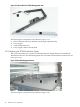
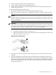
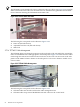

Figure 2-18 TFT7600 Rear Ports
7
8
1
3
2 4 6
5
The following list corresponds to the callouts in Figure 2-18:
1. USB keyboard/mouse
2. USB pass-through (connects to a KVM switch virtual media port)
3. PS2 keyboard
4. PS2 mouse
5. VGA input
6. Power connection
7. Cable tray
8. Back of TFT7600
9. Serial firmware port — not shown (enables updates to TFT7600 firmware)
Note:
The TFT7600 has a USB pass-through port on the front side which is the pass-through to the rear
USB port (see callout 1 in Figure 2-18).
2.7.1.2 Brace Rail and Cable Management Arm
You do not have to remove the brace rail and cable management arm (see Figure 2-19) to service
the TFT7600. However, the power supply or cables might require service. This section describes
the components in the brace rail assembly that might require service. The brace rail (see callout
1 in Figure 2-19) mounts to the adjustable rails. The cable management arm is attached to the
back of the TFT7600 with two 6-32 screws, which must be removed to enable removal of the
TFT7600 for replacement, if necessary.
2.7 KVM and Console Switches 47