
HP Cluster Platform Core Components Overview
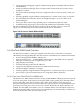
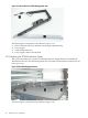

1. Cables routed through the cable management arm
2. Power supply attached to the cable management arm
3. Cables are routed through the cable management arm and exit through the side rail (see
callout 1 in Figure 2-23)
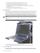
To replace the TFT7600, follow these steps:
1. Extend the TFT7600 forward to the locked position (see Figure 2-17).
2. Disconnect the power supply, VGA, and PS2 keyboard/mouse, cables from the rear of the
unit.
Caution:
Failure to disconnect the power source prior to service of the unit can result in damage to
the power supply or TFT7600. See the TFT7600 Rack-Mount Keyboard and Monitor User Guide
for more information.
Important:
PS/2 cables on the TFT7600 have a locking mechanism to provide a secure cable connection
(see Figure 2-21). You must use proper procedures when disconnecting these cables. See the
TFT7600 Rack-Mount Keyboard and Monitor User Guide for more information.
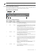
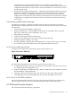
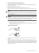
To properly disconnect the keyboard cable, follow these steps:
1. Grasp the housing (see callout 1 in Figure 2-21).
2. Slide the housing back to release the locking mechanism and gently pull to remove the
cable (see callout 2 in Figure 2-21).
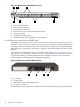
Figure 2-21 PS/2 Housing Lock
3. Disconnect the cable management arm by removing two 6-23 screws from the rear of the
TFT7600.
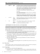
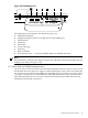
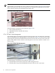
4. Slide the TFT7600 out from the inner rails by simultaneously releasing the slide locks on
both sides of the inner rails (see callout 3 in Figure 2-22). Callout 3 is the approximate position
of where the slide lock release is located. The release mechanisms are white plastic rectangle
knobs on the outside of each inner rail and are clearly visible. The procedure is similar to
releasing a desk drawer.
2.7 KVM and Console Switches 49