HP Cluster Platform Overview Abstract This document describes the benefits, hardware support, software support, and installation considerations of HP Cluster Platform systems.
© Copyright 2012 Hewlett Packard The information contained herein is subject to change without notice. The only warranties for HP products and services are set forth in the express warranty statements accompanying such products and services. Nothing herein should be construed as constituting an additional warranty. HP shall not be liable for technical or editorial errors or omissions contained herein. Acknowledgements Microsoft and Windows are U.S. registered trademarks of Microsoft Corporation.
Contents 1 Concepts...................................................................................................4 Architecture.............................................................................................................................4 Nodes................................................................................................................................4 Console and Administrative Networks...................................................................................
1 Concepts This chapter describes HP Cluster Platform architecture and technology. An HP Cluster Platform is a factory-integrated package of HP ProLiant nodes (servers), management networks, high-speed interconnects, and optional storage. HP Cluster Platform configurations deliver high performance computing. Configurations are based on a common base architecture, which allows for flexible customized systems, including choices for server and interconnect types.
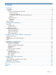
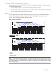
Figure 1 Typical HP Cluster Platform set of nodes 1 3 2 4 1. Control Node 2. Application Nodes 3. Additional node group 4. Additional node group The Control Nodes are also considered a separate node group. A Cluster Platform comprises at least two node groups (Control Node and one other group) and can contain many node groups. NOTE: There is no limit to the number of node groups. However, there is a configuration-dependent maximum number of supported nodes.
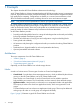
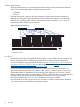
Figure 2 Console Network connections 1 2 2 2 2 1. Console Root switch 2. Console Leaf switches Administrative Network HP Cluster Platforms use a 1 gigabit/second Ethernet (GbE) network to manage and administrate the cluster at the operating system level, for example, image distribution or job management. All nodes are connected to the Administrative Network using a GbE port. The Administrative Network is implemented with one or more GbE switches distributed in the racks with the nodes.
Connecting Console and Administrative Networks Depending on your specific needs, the Console and Administrative Networks can be connected in one of the following ways: • The Console Root switch is connected to the Administrative Root switch. • The Console Root switch is connected to a second Ethernet port on the Control Node, keeping the Console and Administrative Network separate. Regions For very large systems, the cluster is divided into regions.
System Interconnect The System Interconnect is an optional separate network that provides communication between nodes. The two technology options for System Interconnect are: • InfiniBand • Ethernet If System Interconnect is present, all nodes except the Control Node must be connected to it. Although connecting the System Interconnect to the Control Node is optional in an HP Cluster Platform, your operating system software can require that it be connected.
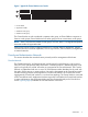
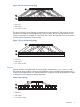
Figure 6 One-to-one fat tree topology 1 2 3 Nodes 1. Root switch 2. Leaf switches 3. “N” number of nodes The second variation on the topology is referred to as two-to-one fat tree. This topology also has symmetrical connections between the Leaf and Spine switches, but has half has many as in the one-to-one topology. For example, if a Leaf switch has n ports, then typically 2n/3 ports connect to nodes and n/3 connect to Spine switches. Figure 7 Two-to-one fat tree topology 1 2 3 Nodes 1.
Physical design The physical design of an HP Cluster Platform is based on modular building blocks that are created when the cluster is built at the factory. These building blocks are defined as follows: • Compute Building Block (CBB) The majority of the cluster consists of Application Nodes that are organized in single-rack modules called CBBs. A CBB typically contains Application Nodes, Administrative Network Leaf switches, Console Network Leaf switches, PDUs, and optionally System Interconnect switches.
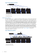
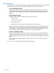
Figure 9 Example of a typical HP Cluster Platform system 1 2 12 3 4 12 5 12 6 14 7 8 9 13 10 12 12 12 1. Additional Node Group 8. Administrative Root switch 2. Administrative Network switches 9. Console Root switch 3. Console Network switches 10. System Interconnect 4. Application Nodes 11. Power distribution units (PDUs) 5. Additional Node Group in UBB 12. Compute Building Blocks (CBBs) 6. Control Node 13. Interconnect Building Block (IBB) 7. Keyboard, video, mouse (KVM) 14.
2 Configuration guidelines This chapter describes HP Cluster Platform configuration guidelines. Hardware Control Nodes Typically, Control Nodes have: • Two multicore processors • At least 1 GB memory per core processor • One or more internal disks • A drive capable of reading DVDs • Redundant power supplies if available • Optional connection to external storage The Control Node is typically connected to the System Interconnect if one is included in the Cluster Platform.
For the latest information on cluster management, see http://h20311.www2.hp.com/HPC/cache/ 278870-0-0-0-121.html and the Unified Cluster Portfolio website at http://h20311.www2.hp.com/ HPC/cache/275420-0-0-0-121.html. HP Cluster Platform supports the following cluster management tools: • HP Insight Cluster Management Utility (Insight CMU)—For more information, see: http://h20311.www2.hp.com/HPC/cache/412128-0-0-0-121.html • Windows HPC Server (HPCS) 2008—For the latest information, see: http://h20311.
3 Supported HP Cluster Platform components This chapter describes the currently supported components used in an HP Cluster Platform. System Interconnects Table 1 (page 14) lists the supported System Interconnects used in an HP Cluster Platform.
Administrative and Console Networks Table 3 (page 15) lists the switches supported for use in the Administrative and Console Networks. Table 3 Supported switches for Administrative and Console Networks Network Vendor Administrative Network Switch model 2910al HP Networking Console Network 2620 For more information about HP Networking switches, see http://h17007.www1.hp.com/us/en/ products/switches/index.aspx.
4 Installation considerations Planning for the installation The customer and HP support share the responsibilities for installation planning. The required installation planning tasks must be scheduled and completed to ensure successful installation of an HP Cluster Platform. Customer responsibilities Prior to an HP Cluster Platform installation, you must: • Understand safety requirements associated with installing an HP Cluster Platform.
• Suitably equipped and trained personnel to assist in heavy lifting. While component removal is not anticipated, post-installation troubleshooting might require the removal of components. WARNING! The weight of some rack-mounted components requires the use of a mechanical lift or at least two people to remove and replace the component in the rack. Before replacing a component, see the component's QuickSpecs at http://www.hp.com/go/quickspecs for weight information.
http://h18000.www1.hp.com/products/quickspecs/12402_div/12402_div.HTML • HP Intelligent Series Rack QuickSpecs, available at http://h18004.www1.hp.com/products/quickspecs/14223_na/14223_na.html nl Power Cluster Platform configurations use a variety of power cords and plugs and you must ensure that your computer room can supply adequate power to your Cluster Platform. The HP Power Calculator utility (http://h30099.www3.hp.com/configurator/calc/ Power%20Calculator%20Catalog.
5 Support and other resources Contacting HP For worldwide technical support information, see the HP support website: http://www.hp.com/support Before contacting HP, collect the following information: • Product model names and numbers • Technical support registration number (if applicable) • Product serial numbers • Error messages • Operating system type and revision level • Detailed questions New and changed information in this edition • This is a new version of the document.
6 Documentation feedback HP is committed to providing documentation that meets your needs. To help us improve the documentation, send any errors, suggestions, or comments to Documentation Feedback (docsfeedback@hp.com). Include the document title and part number, version number, or the URL when submitting your feedback.
Glossary A Administrative Network 1GbE network used to manage administrative functions. Application Node Nodes (servers) used for running computational tasks. B building blocks Units of the Cluster Platform (a single rack) used to house like nodes and associated hardware by function. See CBB, UBB, or IBB. C CBB Compute Building Block—Unit of a Cluster Platform comprised of Application Nodes. Console Network An Ethernet network used for console functions.
S SAN Storage Area Network. System Interconnect An optional Ethernet or InfiniBand network that provides communication between nodes. U UBB Utility Building Block—unit of a Cluster Platform comprised of supporting infrastructure, such as Control Node, Administrative and Console Network root swtiches, and KVM. UFM Unified Fabric Manager (Voltaire).
Index A N Administrative Network, 6 Administrative Root switch, 10 Application Node, 4, 10, 12 network Administrative, 6 Console, 5 Ethernet, 9 InfiniBand, 8 regions, 7 supported Administrative and Console, 15 System Interconnect, 8 node groups, 4, 5, 10 nodes Application, 4, 12 Control, 4, 12 group, 4 typical set, 4 B building blocks, 10 C CBB, 10 clusters base modules, 10 management, 12 operating systems, 12 Compute Building Block see CBB configurations for HP Cluster Platform, 4 Console Network, 5 C
topology one-to-one fat tree, 8 tree, 9 two-to-one fat tree, 9 tree topology, 9 two-to-one fat tree topology, 9 typographic conventions, 19 U UBB, 10 Utility Building Block see UBB W warning rack stability, 18 24 Index