
HP Cluster Platform Overview

Physical design
The physical design of an HP Cluster Platform is based on modular building blocks that are created
when the cluster is built at the factory. These building blocks are defined as follows:
• Compute Building Block (CBB)
The majority of the cluster consists of Application Nodes that are organized in single-rack
modules called CBBs. A CBB typically contains Application Nodes, Administrative Network
Leaf switches, Console Network Leaf switches, PDUs, and optionally System Interconnect
switches.
• Utility Building Block (UBB)
The UBB contains supporting infrastructure components including:
◦ Control Node
◦ Administrative Root switch
◦ Console Root switch
◦ Keyboard, video, and mouse (KVM) connected to the Control Node
Additional space in the UBB can be used for other components, such as disk storage systems.
The rack space usage is defined for each specific HP Cluster Platform implementation or is
reserved space. To ensure adequate airflow and cooling, HP recommends that you not use
any unoccupied rack space for components that are not part of the cluster.
• Interconnect Building Block (IBB)
IBB racks contain System Interconnect switches. Spine/Core switches are typically placed in
the IBB; Leaf switches can be placed in the IBB or distributed into CBB racks with nodes. In a
small configuration, System Interconnect switches can be placed in the UBB to conserve floor
space.
An IBB may contain multiple System Interconnect switches and a cluster may contain more
than one IBB.
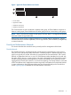
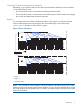
Figure 9 (page 11) illustrates a typical HP Cluster Platform system.
10 Concepts