
HP Cluster Platform Overview


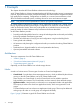
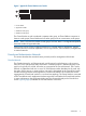
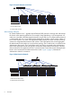
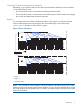
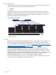
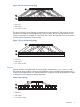
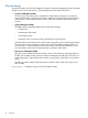

Figure 6 One-to-one fat tree topology
Nodes
1
2
3
1. Root switch
2. Leaf switches
3. “N” number of nodes
The second variation on the topology is referred to as two-to-one fat tree. This topology also has
symmetrical connections between the Leaf and Spine switches, but has half has many as in the
one-to-one topology. For example, if a Leaf switch has n ports, then typically 2n/3 ports connect
to nodes and n/3 connect to Spine switches.
Figure 7 Two-to-one fat tree topology
Nodes
1
2
3
1. Root switch
2. Leaf switches
3. “N” number of nodes
Ethernet
Ethernet networks are implemented as tree topologies as illustrated in Figure 8 (page 9). With
this topology, there are fewer connection paths between nodes on different Leaf switches than in
a fat tree. Consequently there is a greater potential for congestion, though the performance impact
is dependent on the network use by the application.
Figure 8 Tree topology
Nodes
1
2
3
1. Root switch
2. Leaf switches
3. “N” number of nodes
Architecture 9