
HP Cluster Platform Server and Workstation Overview
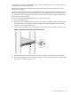
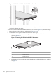
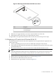
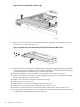
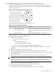
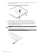
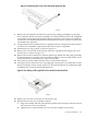
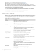

Figure 3-14 Removing the Cover of the Full-Length Expansion Slot
HPTC-0163
8. Remove the PCI expansion board from its protective packaging, handling it by the edges.
Some expansion boards can only be installed in one slot but other boards can be configured
to fit in either slot by replacing the default bracket (attached to the board) with a different
sized bracket. The different sized bracket and instructions on how to attach it to the board
is included in the option kit.
9. Verify that the board’s default bracket is compatible with the configuration of the selected
slot. If it is not compatible, replace the bracket with one that is compatible.
10. Pull the PCI riser cage upward, as shown in Figure 3-9.
11. Remove the screw located on the left side of the riser cage before removing the PCI card
from the slot, as shown in Figure 3-10.
12. Remove the new PCI card from its antistatic plastic bag. Handle the card gently, preferably
by the front panel or card edges. Do not touch the connectors. The front panel of the card is
the metal plate that contains the port connector and LEDs.
13. Record the card serial number located on the card for future reference.
14. Insert the new PCI card into the riser cage, applying even pressure to seat the board securely.
Be sure the adapter is fully seated. Figure 3-15 shows the installation of a full-length 64-bit,
133 MHz PCI-X card in an HP ProLiant DL145 G2.
Figure 3-15 Installing a Full-Length PCI Card in the HP ProLiant DL145 G2
HPTC-0164
15. Replace the screw that secures the card in the riser cage.
16. Reinstall the PCI riser cage assembly as follows:
a. Align the assembly with the system board expansion slots, then press it down to ensure
full connection to the system board.
b. Tighten the two captive thumbscrews to secure the assembly to the chassis.
3.1 HP ProLiant DL145 109