
HP Cluster Platform Server and Workstation Overview

1. Attach a grounding strap to your wrist or ankle and a metal part of the chassis.
2. Press the Power button to power down the server. When the server powers down, the system
power LED turns off.
3. Disconnect the AC power cord from the AC outlet.
Note:
The front panel Power button does not completely shut off system power. Portions of the
power supply and some internal circuitry remain active until AC power is removed.
4. Remove the server from the rack, as described in Section 3.2.1.
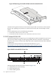
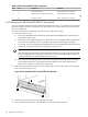
5. Remove the access panel from the server, as shown in Figure 3-20.
6. Disconnect the cable attached to the PCI card.
7. Lift and remove the appropriate PCI riser board assembly from the chassis as described in
Section 3.2.5.1.
8. Remove the PCI expansion board from its protective packaging, handling it by the edges.
9. Verify that the board’s default bracket is compatible with the configuration of the selected
slot. If it is not compatible, replace the bracket with one that is compatible.
10. Remove the new PCI card from its antistatic plastic bag. Handle the card gently, preferably
by the front panel or card edges. Do not touch the connectors. The front panel of the card is
the metal plate that contains the port connector and LEDs.
11. Record the card serial number located on the card for future reference.
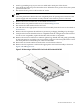
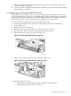
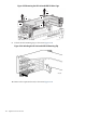
12. Remove the PCI expansion card from the appropriate riser board assembly as shown in
Figure 3-26 and Figure 3-27.
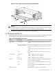
Figure 3-26 Removing a Full-Sized PCI Card in the HP ProLiant DL145 G3
3.2 HP ProLiant DL145 G3 121