
HP Cluster Platform Server and Workstation Overview
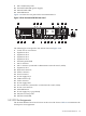

9. NIC 1 link/activity LED
10. External health LED (power supply)
11. Internal health LED
12. UID LED button
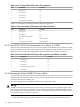
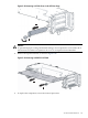
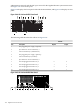
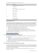
Figure 3-39 shows the rear panel of the ProLiant DL385 G2.
Figure 3-39 HP ProLiant DL385 G2 Rear Panel
1
2
3
4
5
6 7
8
9
10
11
12
13
14
20
18
15
19
17
16
21
22
The following list corresponds to the callouts shown in Figure 3-39:
1. T-10/T-15 Torx screwdriver
2. Expansion slot 5
3. Expansion slot 4
4. Expansion slot 3
5. Expansion slot 2
6. External option blank
7. NIC 2 connector
8. NIC 1 connector (connected to administrative network switch, AES1)
9. Expansion slot 1
10. Keyboard connector
11. Mouse connector
12. Serial connector
13. Power supply bay 2
14. USB connectors (2)
15. Video connector
16. Power supply LED
17. iLO 2 connector (connected to console network switch, CES1)
18. Power cord connector
19. UID LED button
20. Power supply bay 1 (populated)
21. NIC/iLO 2 activity LED
22. NIC/iLO 2 link LED
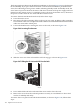
3.5.2 PCI Slot Assignments
The ProLiant DL385 G2 has five PCI slots on the rear of the chassis. Table 3-10 summarizes the
PCI Express slot assignments.
3.5 HP ProLiant DL385 G2 131