
HP Cluster Platform Server and Workstation Overview

Note:
When the server powers down, the Power button LED changes from green to amber,
indicating Standby mode. In Standby mode, the server removes power from most electronics
and drives, but portions of the power supply and some internal circuitry remain active until
AC power is removed.
3. Disconnect the AC power cord, first from the AC outlet and then from the server.
4. Remove the server from the rack, as shown in Section 3.8.1.
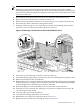
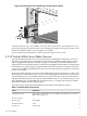
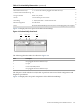
5. Remove the access panel from the server, as shown in Figure 3-57, and locate the PCI slot.
6. Disconnect any cables connected to the expansion board.
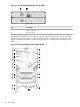
7. Using the callouts in Figure 3-59 as a guide, press the PCI card retaining clip toward the
front of the server to lock it in the open position (see callout 1).
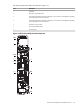
Figure 3-59 Removing a PCI Card from an HP ProLiant DL585 G2 Server
1
2
3
4
8. Press down on the expansion slot latch to release it (callout 2).
9. Unlock the retaining clip (callout 3), if necessary, such as for full-length PCI expansion cards.
10. Remove the board from the slot (callout 4).
11. Remove the new PCI card from its antistatic plastic bag. Handle the adapter gently, preferably
by the front panel or card edges. Do not touch the connectors. The front panel of the adapter
is the metal plate that contains the port connector and LEDs.
12. Record the adapter card serial number located on the card for future reference.
13. Insert the new PCI card in the slot, applying even pressure to seat the board securely. Be
sure the adapter is fully seated.
14. Close the expansion slot latch (callout 2).
15. Close the PCI retaining clip (callout 3), if necessary.
16. Reinstall the access panel, reversing the steps in Section 3.8.1.
17. Replace the server in the rack, reversing the steps in Section 3.8.1.
3.8 HP ProLiant DL585 G2 151