
HP Cluster Platform Server and Workstation Overview
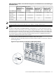

Note:
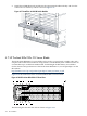
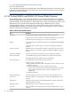
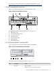
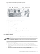
For information on the location of LEDs and ports on individual interconnect modules, see the
documentation that ships with the interconnect module.
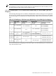
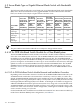
4.4.4 HP BladeSystem c-7000 Interconnect Module Bay to Server Blade Type Port
Mapping
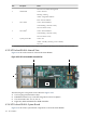
The following table maps the server blade's embedded NICs and mezzanine port slot assignments
for various server blade types (single density full-height, single density half-height, and double
density half-height server blades) to the HP BladeSystem c-7000 enclosure interconnect module
bays.
Table 4-3 HP BladeSystem c-7000 Interconnect Module Bay to Server Blade Type Port Mapping
Single-Density Full-Height
Server Blade
Double-Density
Half-Height Server Blade
- Server B
Double-Density
Half-Height Server Blade
- Server A
Single-Density
Half-Height Server
Blade
Interconnect
Bay
NIC 3 (embedded)
N/ANIC 1 (embedded)
NIC 1 (embedded)
1
NIC 1 (embedded)
NIC 4 (embedded)NIC 1 (embedded)
N/A
NIC 2 (embedded)
2
NIC 2 (embedded)
Mezzanine slot 1, port 1
N/ANIC 2 (embedded)
Mezzanine slot 1,
port 1
3
NIC 2 (embedded)N/A4
Mezzanine slot 2, port 1
N/AMezzanine port 1
Mezzanine slot 2,
port 1
5
Mezzanine slot 3, port 2
6
Mezzanine slot 2, port 2
Mezzanine port 1N/A
Mezzanine slot 2,
port 2
7
Mezzanine slot 3, port 1
8
For more information on mapping to interconnect ports, see the HP BladeSystem c7000 Enclosure
Setup and Installation Guide.
4.4 HP BladeSystem c-Class Enclosure Overview 171