
HP Cluster Platform Server and Workstation Overview
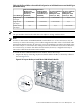
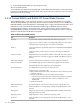
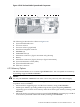

1. Server B Power On/Standby button and power LED
2. Server B UID LED
3. Server B health LED
4. Server B NIC link and activity LED
5. Server B serial label pull tab
6. Server B HP c-Class Blade SUV cable connector
7. Server blade handle
8. Server A Power On/Standby button and power LED
9. Server A UID LED
10. Server A health LED
11. Server A NIC link and activity LED
12. Server A serial label pull tab
13. Server A HP c-Class Blade SUV cable connector
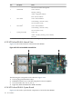
For an internal view of the HP ProLiant BL2x220c G5 and additional information, such as the
system board layout and installing mezzanine HCAs, see the HP ProLiant BL2x220c Generation
5 Server Maintenance and Service Guide:
http://bizsupport.austin.hp.com/bc/docs/support/SupportManual/c01462866/c01462866.pdf
4.8 HP ProLiant BL260c G5 Server Blade
The HP ProLiant BL260c G5 server blade can be used as a control node, a utility node, and a
compute node in HP Cluster Platform configurations.
For the features and specifications of the HP ProLiant BL260c G5, see the QuickSpecs on the HP
website:
http://h18004.www1.hp.com/products/quickspecs/13026_na/13026_na.pdf
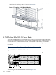
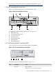
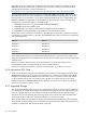
Figure 4-19 shows the front view of a ProLiant BL260c G5 server blade.
Figure 4-19 HP ProLiant BL260c Front View
3
1 2 8 10
4 5 6 7 9
The following list describes the callouts shown in Figure 4-19:
1. Serial label pull tab
2. Local I/O connector
3. UID LED/button
4. Health LED
5. NIC 1 LED
6. NIC 2 LED
7. Hard drive activity LED
8. Release button
4.8 HP ProLiant BL260c G5 Server Blade 175