
HP Cluster Platform Server and Workstation Overview
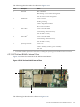
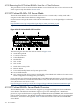
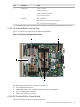
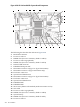

Figure 4-38 HP ProLiant BL685c System Board Components
2
1
3 4 5 6 7
8
9
10
11
12
13
14
15
161718192021222324
25
26
The following list describes the callouts in Figure 4-38:
1. Bezel LED connector
2. Processor socket 4
3. DIMM slots (Processor 4 memory banks G and H)
4. Processor socket 2 (populated)
5. DIMM slots (Processor 2 memory banks C and D)
6. Internal USB connector
7. Embedded dual-port NIC
8. Mezzanine connector 2 (Type I or Type II mezzanine)
9. Mezzanine connector 1 (Type I mezzanine only)
10. Enclosure connector 1
11. System board thumbscrew
12. Mezzanine connector 3 (Type I or Type II mezzanine)
13. Enclosure connector 2
14. System board thumbscrew
15. Embedded NIC
16. Embedded NIC
17. Smart Array E200i cache module (under mezzanine card 3)
18. SAS cable
19. Processor socket 1 (populated)
20. DIMM slots (Processor 1 memory banks A and B)
21. System battery
22. DIMM slots (Processor 3 memory banks E and F)
23. Processor socket 3
200 Server Blades