
HP Cluster Platform Server and Workstation Overview
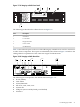
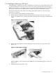
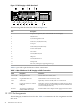
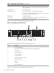

Table 1-3 HP Integrity rx2600 Ports Used in Clusters
Cluster Cabling Name and DescriptionNode RolePort LabelCallout
Power input 1 is used for the single power connection.AllPWR 11
MP Console, CES – The management processor Ethernet LAN
connection. This 10/100 Base-T port is connected to the root console
switch (CES1) in the Utility Building Block (UBB).Control and utilityMP 10/1002
NIC2 (Administrative, AES) – The Gigabit Ethernet Port . This
Base-T 10/100/1000 Ethernet port is connected to the root
administrative switch (AES1) in UBB.Control and utilityLAN Gb3
Video Port. This port is optionally connected to the cluster's KVM
consoleControlVGA4
NIC1 – The LAN Ethernet Port. This 10/100 Base-T Ethernet port
is optionally connected to the site WAN, enabling remote
connections to the cluster's control node.AllLAN 10/1005
Upper of the two stacked USB ports. Use this port only for the
optional connection to the KVM mouse and keyboard. Do not use
the ports labelled keyboard and mouse.ControlUSB6
The PCI-X 133 slot in which the interconnect card is installed. Slot
0 is at the top and slot 3 is at the bottom.
Optional for the
control nodePCI Slot 07
The node role column in Table 1-3 defines whether the connection is used in an application node,
a control node, or a utility node.
Refer to the server documentation for definitions of the remaining ports, but be aware that you
should never make additional connections to a server that is configured for a specific role in the
cluster.
1.2.1 Network Port Assignments
The HP Integrity rx2600 has three embedded network ports:
• Management processor (MP) 10/100 Ethernet port, connected to the cluster's console network
switch.
• NIC1 10/100 Ethernet port, optionally connected to the local WAN, enabling remote access.
• NIC2 Gigabit Ethernet port, connected to the administrative network.
Figure 1-9 HP Integrity rx2600 Network Ports
1 2
3
4
6
7
5
The following list describes the callouts in Figure 1-9.
32 Itanium Processor Servers