
HP Cluster Platform Server and Workstation Overview
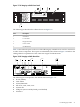
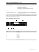
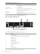

1. LAN 10/100 (management port)
2. Management card
3. VGA
4. GSP reset (soft)
5. GSP reset (hard)
6. LAN 10/100 (NIC 1)
7. LAN Gb (NIC 2)
The ports, their labels, and the corresponding HP Cluster Platform cabling identifiers are shown
in Figure 1-9.
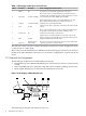
A single embedded gigabit Ethernet port is available on the HP Integrity rx2600 (NIC2). This
Gigabit Ethernet port is dedicated to the cluster's administrative network. This connection differs
from the HP Integrity rx4640 where NIC1 is the connection to the cluster's administrative network.
Refer to the cluster's cabling tables for more information.
1.2.2 Supported Memory Configurations
HP Cluster Platform does not enforce any memory configuration rules on the HP Integrity rx2600
nodes, other than those associated with the server used. For the HP Integrity rx2600 these rules
are:
• The system has 12 memory slots for installing DDR SDRAM memory modules.
• The system supports a maximum of 12 GB of memory and a minimum of 512 MB.
• Memory modules can either be 256 MB, 512 MB, or 1 GB, and they must be arranged as
ordered pairs of equal size. For example, if you place a 1 GB memory module in slot 0A,
you must insert a 1 GB memory module in slot 0B.
• Memory in the HP Integrity rx2600 must be loaded in quads. This means that you must load
two memory cards per cell. For example, using the loading order provided above, place two
DIMMs in slots 0A and 0B of memory cell 0, and two DIMMs in slots 1A and 1B in memory
cell 1.
• DDR SDRAM must be loaded as matched pairs. To determine if the DIMMs are matched
pairs, look at the HP part number on the DIMMs. If the HP part numbers match, then the
DIMMs can be loaded together as a pair.
• You can mix module sizes in the system, provided that DIMMs in each pair share the same
HP part number. For example, it is acceptable to load a pair of 256 MB DIMMs in slots 0A
and 0B, a pair of 1 GB DIMMs in slots 1A and 1B, then load 512 MB DIMMs in slots 2A, 2B,
3A, and 3B.
• You must install the first DDR SDRAM matched pair in memory cell 0 and in the slots labeled
DIMM 0A and DIMM 0B. Load the second matched pair in memory cell 1 and in the slots
labeled DIMM 1A and DIMM 1B. Continue loading successive matched pairs using the
sequence described in Table 1-4.
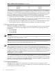
Table 1-4 Memory Slot Loading Order
Memory Cell 1Load OrderMemory Cell 0Load Order
A Slots
DIMM 1A2ndDIMM 0A1st
DIMM 5A6thDIMM 4A5th
DIMM 3A4thDIMM 2A3rd
B Slots
DIMM 1B2ndDIMM 0B1st
1.2 HP Integrity rx2600 33