
HP Cluster Platform Server and Workstation Overview

3. Disconnect the AC power cord, first from the AC outlet and then from the server.
Warning!
Ensure that the system is powered off and all power sources have been disconnected from
the server prior to performing this procedure.
Voltages are present at various locations within the server whenever an AC power source
is connected. This voltage is present even when the main power switch is in the off position.
Failure to observe this warning may result in personal injury or damage to equipment.
4. Remove the server from the rack.
5. Remove the access panel from the server.
6. Disconnect all internal and external cables attached to the I/O cards in the I/O backplane
assembly.
Caution:
Record the slot location of all PCI cards as they are removed. Depending on the operating
system, replacing the PCI cards in a different location may require system reconfiguration
and may cause boot failure.
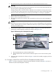
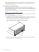
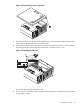
7. Loosen the two captive screws as shown by callout 1 in Figure 1-18. Check the removal
instructions on the backplane assembly (see callout 3 in Figure 1-18).
Figure 1-18 Removing the I/O Backplane Assembly
3
2
1
a. Press the blue button to release the black knob.
b. Turn the black knob counterclockwise until the captive screw is free from the system
board.
8. Using the sheet metal tab (see callout 2 in Figure 1-18) lift the assembly straight up and out
of the server.
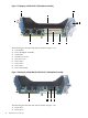
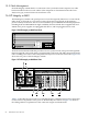
1.4.2.1 Integrity rx2660 PCI–X and PCI-X/PCI-E I/O Backplane Assembly Options
Figure 1-19 shows an Integrity rx2660 PCI-X I/O backplane assembly and Figure 1-20 shows a
mixed PCI-X/PCI-E I/O backplane assembly.
1.4 HP Integrity rx2660 43