
HP Cluster Platform Server and Workstation Overview
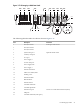
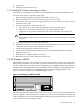
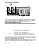
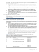
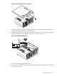
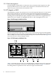

Figure 1-22 HP Integrity rx3600 Rear View
1
6543
2
Table 1-11 describes the ports on the rear of the HP Integrity rx3600 that are used for connections
to other cluster components. These ports are identified by the callouts in Figure 1-22. Refer to
the cabling tables for explanations of the connection origins and destinations.
Table 1-11 HP Integrity rx3600 Ports Used in Clusters
Cluster Cabling Name and DescriptionPort LabelCallout
When used as a control node only, both power supplies are used to provide
redundancy. Otherwise, utility nodes use only PWR 0.
PWR 0 and PWR 11
VGA Video Port. When used as a control node, this port is optionally connected
to the cluster's KVM console.
Screen Icon2
Use only the upper of the two stacked USB ports. When this server is used as a
control node, use USB 1 port for the optional connection to the KVM mouse and
keyboard. Do not use the ports labeled keyboard and mouse.
USB ports3
MP (Console, CES). The MP Ethernet LAN connection. This 10/100 Base-T port is
connected to the root console switch (CES1) in the UBB.
MP LAN4
NIC1 (Administrative, AES) – The gigabit Ethernet port in PCI slot 2. This
10/100/1000 Base-T Ethernet port is connected to the root administrative switch
(AES1) in the UBB.
LAN Gb5
PCI (slot 8).N/A6
The spare Ethernet port in PCI slot 2 is designated NIC 2 and might also be used for an optional
connection to the site WAN, depending on the server's role.
Refer to the server documentation for definitions of the remaining ports, but be aware that you
should never make additional connections to a server that is configured for a specific role in the
cluster.
1.5.1 Supported Memory Configurations
The HP Cluster Platform does not enforce any memory configuration rules on the control node
and utility nodes other than those associated with the server used. You can use DIMMs of 256
46 Itanium Processor Servers