
HP Cluster Platform Server and Workstation Overview
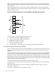

When a PCI Express HCA is used in slot 3 of the ProLiant DL380 G5, mount the appropriate
cable management bracket in the top hole (callout 5 in Figure 2-41) of the lower U location (callout
2 in Figure 2-41).
When a PCI Express HCA is used in slot 4 of the ProLiant DL380 G5, mount the appropriate
cable management bracket in the bottom hole (callout 4 in Figure 2-41) of the upper U location
(callout 1 in Figure 2-41).
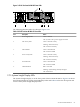
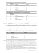
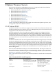
Figure 2-41 Rack Mounting Holes for ProLiant DL380 G5 Cable Management Brackets
T
M
B
T
M
B
1
2
3
5
6
4
The following list describes the callouts in Figure 2-41:
1. Upper U location (top, middle, and bottom)
2. Lower U location (top, middle, and bottom)
3. Middle hole of upper U location
4. Bottom hole of upper U location
5. Top hole of lower U location
6. Two U locations — 2U is required to rack mount the HP ProLiant DL380 G5
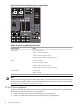
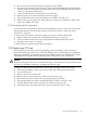
2.7.9 Removing the Server from the Rack
To access internal components in the ProLiant DL380 G5, you must first power down the server
and then remove it from the rack. All of the servers in the cluster are secured to the rack on a
sliding rail.
The front panel power button on the ProLiant DL380 G5 toggles power between On and Standby.
If you press the Power On/Standby switch to power down the server, the Power On/Off LED
changes from green to amber, indicating standby mode. In Standby mode, the server removes
power from most electronics and drives; portions of the power supply and some internal circuitry
remain active. If you press the Unit Identification switch on the front panel, an LED illuminates
blue on the server front and rear panels.
The rear Unit Identification LED identifies the server being serviced.
To completely remove all power, disconnect the power cord first from the AC outlet and then
from the server.
When performing these tasks, heed the warnings and cautions listed in “Important Safety
Information” (page 23).
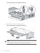
To remove a server from the rack, follow these steps:
96 Xeon Processor Servers