HP Cluster Platform Workgroup System Tower Hardware Installation Guide HP Part Number: A-CPWST-1B Published: February 2008
© Copyright 2008 Hewlett-Packard Development Company, L.P. The information contained herein is subject to change without notice. The only warranties for HP products and services are set forth in the express warranty statements accompanying such products and services. Nothing herein should be construed as constituting an additional warranty. HP shall not be liable for technical or editorial errors or omissions contained herein.
Table of Contents About This Document.........................................................................................................9 Intended Audience.................................................................................................................................9 New and Changed Information in This Edition.....................................................................................9 Document Organization.....................................................................
List of Figures 1-1 1-2 1-3 1-4 3-1 3-2 3-3 3-4 3-5 3-6 4-1 A-1 A-2 A-3 A-4 A-5 A-6 Workgroup System Tower Example Front View..........................................................................14 Workgroup System Tower Example Rear View............................................................................15 HP GbE2c Ethernet Blade Switch..................................................................................................17 4X DDR InfiniBand Interconnect.............................
List of Tables 1-1 HP GbE2c Ethernet Blade Switch for c-Class BladeSystem User and Service Documentation....
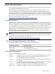
About This Document This document provides preparation tasks and hardware installation information for the HP Cluster Platform Workgroup System Tower. Workgroup System Tower configurations are easy-to-order, preconfigured, single c-Class enclosure (c3000) cluster solutions supporting either InfiniBand or gigabit Ethernet system interconnects. When ordering a Workgroup System Tower, you can specify installation support from HP Global Services, or complete the onsite installation procedures yourself.
Typographic Conventions This document uses the following typographic conventions: Reader Notes NOTE: Content of the note. Notes provide additional information, supplementing the adjoining content or emphasizing points of information. Reader Warnings WARNING! Content of the warning. A warning calls attention to important information that if not understood or followed will result in personal injury or nonrecoverable system problems. Reader Cautions CAUTION: Content of the caution.
Documentation Updates and Release Notes Documentation updates and release notes (if applicable) are provided on the HP High Performance Computing documentation website: http://www.docs.hp.com/en/highperfcomp.html Use the release date of a document to determine that you have the latest version.
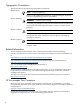
1 Cluster Platform Workgroup System Tower Overview The HP Cluster Platform Workgroup System Tower is delivered to you factory assembled and ready for deployment. It is available with a choice of pre-installed software for cluster management. The extensive array of software tools featured in the Unified Cluster Portfolio are supported on the Workgroup System Tower. For more information, go to the Unified Cluster Portfolio overview: http://h20311.www2.hp.com/HPC/cache/275420-0-0-225-121.
1.1 Workgroup System Tower Views The Workgroup System Tower ships with the server blades and all of the factory integrated modules installed. Figure 1-1 shows an example front view of the Workgroup System Tower. Note: HP Cluster Platform Workgroup System is available from HP Sales Representatives and HPC-Certified Resellers, utilizing Cluster Platform Express configurators. Quotes can be requested by submitting a form available at the following web site: http://h20311.www2.hp.com/HPC/cache/276453-0-0-0-121.
Figure 1-2 Workgroup System Tower Example Rear View 8 9 7 6 10 5 4 3 3 2 1 9 The following list describes the callouts in Figure 1-2: 1. Local KVM interface 2. HP GbE2c Ethernet switch installed in interconnect module bay 1 (IMB1) 3. Active cool fans 4. Interconnect module bay 2 (reserved for potential future use) 5. Enclosure uplink and service port 6. Enclosure downlink 7. iLO/Onboard Administrator port 1 8. iLO/Onboard Administrator port 2 (reserved for future use) 9. Power supplies 10.
Note: Control and compute nodes must belong to the same processor family. For example, control nodes that use AMD Opteron processors must be used if you are using the ProLiant BL465c as the compute node. • Networks: The networks included in a Workgroup System Tower configuration are: — Administrative network: An administrative network eases cluster administration and management functions, such as managing a user's applications.
The HP GbE2c switch is installed in interconnect module bay 1 (IMB1) of the Workgroup System Tower. It can be used as the system interconnect and also provides the infrastructure for the administration and console network in Workgroup System Tower configurations. Figure 1-3 shows an HP GbE2c Ethernet Blade Switch for c-Class BladeSystem. Figure 1-3 HP GbE2c Ethernet Blade Switch 1 2 3 5 4 6 The following list describes the callouts in Figure 1-3: 1. Reset button 2. Health LED 3. UID LED 4.
1.2.1.2 HP 4X DDR InfiniBand Interconnect, and InfiniBand Mezzanine HCAs The HP 4X DDR (dual date rate) InfiniBand interconnect for HP BladeSystem c-Class is a double-wide interconnect module for the c-Class enclosure. It is based on the Mellanox InfiniScale III 4X DDR InfiniBand switch chip. The 4X DDR InfiniBand interconnect for HP BladeSystem c-Class provides 24 InfiniBand 4X DDR ports with 20 Gbps port-to-port connectivity.
mezzanine HCA be plugged into the x8 PCI-Express connector on the server blade. The InfiniBand dual-port mezzanine HCA is connected to the 4X DDR InfiniBand interconnect module that is installed in interconnect module bays 3 and 4 of the Workgroup System Tower through the c3000 enclosure midplane. HP also offers a single-port 4X DDR InfiniBand mezzanine PCI-Express HCA for c-Class server blades. Subnet Management A subnet manager is required to manage and control an InfiniBand fabric.
2 Workgroup System Tower Pre-installation Procedures This chapter discusses the following pre-installation topics: • Pre-installation procedures (see Section 2.1) • Site recommendations (see Section 2.2) • Power examples (see Section 2.3) 2.1 Pre-installation Procedures HP recommends using an HP approved configurator. Contact an HP sales representative for information on Configure to Order (CTO) product offerings and requirements. The Workgroup System Tower pre-installation procedures are: 1. 2.
2.3 Power Examples There are several power issues to consider before installing a Workgroup System Tower. HP recommends using the HP BladeSystem Power Sizer tool to determine the potential power draw for a Workgroup System Tower configuration. Go to: http://h71019.www7.hp.com/ActiveAnswers/cache/347628-0-0-0-121.html HP also recommends that you consult with your HP sales representative who should be familiar with the HP BladeSystem Power Sizer tool and also review the various power examples available.
3 Unpacking and Removing a Workgroup System Tower from a Pallet This chapter describes how to unpack and remove the Workgroup System Tower from a pallet. To unpack and remove the Workgroup System Tower from a pallet, follow these steps: 1. Move the pallet to the installation location and leave several feet of space to move around the pallet. Note: Carton graphics provide the instructions on how to unpack the Workgroup System Tower and to open the top of the box first. 2.
Figure 3-2 Remove the Box 1 5. Remove the front section of the bottom cushion (callout 2) along with the ramp (callout 1), as shown in Figure 3-3. Figure 3-3 Remove the Ramp and Front Cushion 1 2 6. 24 Attach the ramp to the plywood deck using the velcro strips, as shown by callout 1 in Figure 3-4.
Note: The box clips will need to be folded out of the way to lay the ramp down. Figure 3-4 Attach the Ramp 1 1 Warning! The Workgroup System Tower is heavy (300+ pounds). You might require a second person to assist you with this step.
7. Gently roll the unit down the ramp, as shown by callout 1 in Figure 3-5 and Figure 3-6. Figure 3-5 Roll the Unit Down the Ramp 1 Figure 3-6 Roll the Unit to the Installation Location 1 Proceed to Chapter 4 and start up the system.
4 Installation and Start-up The Workgroup System Tower is integrated and factory tested before shipment to your site. The operating system software is installed at the factory. To power-on your system after you have inspected the unit, follow these steps: Warning! Be sure that all circuit breakers are locked in the off position before connecting any power components. 1. 2. 3. Connect the power cables to the power supply, if necessary. Connect the power cables to the power source or to a PDU.
Note: If your site's network (backbone) cannot handle 1Gb/s, the HP GbE2c Ethernet switch can work at 100Mb/s. The intention is for traffic to the external network to be routed through NIC2 on the control node server blade.
of the HP GbE2C Ethernet switch that are connected to NIC1 of the servers (ports 1-8 on the switch) and the switches management interface. By default, all ports are members of VLAN1. Note: The following procedure requires a PC connection to the OA module. See the section titled Cabling the enclosure beginning on page 38 of the HP BladeSystem c3000 Tower Setup and Installation Guide on the HP website: http://bizsupport.austin.hp.com/bc/docs/support/SupportManual/c01310294/c01310294.
— — • compatible Linux is also included with the XC System Software management option below. HPC 8 packs require purchase of one 10-incident Care Pack from HP Services, unless systems are covered by broad HP Service agreement for Linux support. Microsoft® Windows Server™ 2003, Compute Cluster Edition (included with Windows Compute Cluster Server).
A Workgroup System Tower High-Line Power Examples Warning! Be sure that all circuit breakers are locked in the off position before connecting any power components. Caution: HP recommends that no more than two power supplies be plugged into a single power strip. Important: The configurations shown in this appendix are examples only and do not show all possible combinations of PDUs, UPS, and power cords. C20-C13 power cords are not supplied by HP.
Figure A-1 Example Configuration 1: 4kVA, N+N Redundant Enclosure with a 32A International PDU 2 3 1 2 3 3 3 6 7 6 6 7 5 7 4 6 7 5 4 The following list describes the callouts in Figure A-1: 1. Workgroup System Tower rear view 2. 1200W power supplies (six) 3. C13-C14 power cords (six) 4. PDU power cord to site power 5. 32A International PDU (252663-B31 IEC 309-32A) (two) 6. C13 extension bar (power strips) plugged into the 32A PDU (four) 7.
Figure A-2 Example Configuration 2: 2.7kVA, N+N Redundant Enclosure with 16A PDU, C20-C13 Power Cords (not supplied by HP) 2 3 1 3 2 3 3 5 4 5 4 The following list describes the callouts in Figure A-2: 1. Workgroup System Tower rear view 2. 1200W power supplies (six) 3. Four C20-C13 power cords (not supplied by HP). 4. PDU power cords to site power (two) 5.
Figure A-3 Example Configuration 3: 3kVA, N+1 Redundant Enclosure with a 16A PDU, C20-C13 cords (not supplied by HP) 2 3 1 3 2 3 4 3 5 The following list describes the callouts in Figure A-3: 1. Workgroup System Tower rear view 2. 1200W power supplies (six) 3. Four C20-C13 power cords (not supplied by HP) 4. 16A PDU 5.
Figure A-4 Example Configuration 4: 5kVA - 7kVA, N+1 Redundant Enclosure with 32A PDU, and C13 Extension Bars 3 3 2 1 2 3 3 3 7 7 7 4 4 5 4 6 The following list describes the callouts in Figure A-4: 1. Workgroup System Tower rear view 2. 1200W power supplies (six) 3. Six C13–C14 power cords 4. Power strip cords connected to the PDU (three) 5. 32A International PDU (252663-B31 IEC 309-32A) 6. PDU power cord to site power 7.
Figure A-5 Example Configuration 5: 5kVA, N+N Redundant Enclosure with 16A 3-Phase PDU, C20-C13 Power Cords (not supplied by HP) 3 3 3 2 1 2 3 5 3 3 4 The following list describes the callouts in Figure A-5: 1. Workgroup System Tower rear view 2. 1200W power supplies (six) 3. Six C20-C13 power cords (not supplied by HP) 4. 16A 3-phase PDU, AF513A 5.
Figure A-6 Example Configuration 6: 5kVA, N+1 Redundant Enclosure with 16A 3-Phase PDU, and C20-C13 Power Cords (not supplied by HP) 3 3 2 1 2 3 5 3 3 4 The following list describes the callouts in Figure A-6: 1. Workgroup System Tower rear view 2. 1200W power supplies (six) 3. Five C20-C13 power cords (not supplied by HP) 4. 16A 3-phase PDU, AF513A 5.
B Configuration Rules for Workgroup System Tower This appendix provides the configuration rules for Workgroup System Tower configurations and contains the following sections: • Workgroup System Tower device and interconnect bays (see Section B.1) • Workgroup System Tower fan bays (see Section B.2) B.1 Workgroup System Tower Device and Interconnect Bay Rules The following tables summarize the use of the device bays and interconnect bays for the Workgroup System Tower.
Index about this document, 9 administrative network configuring VLAN for, 28 audience, 9 configuration examples, 31 high-speed interconnect, 18 HP Cluster Platform architecture, 15 website, 10 HPC (see High-Performance Computing) C I c3000 software, 29 cluster configurations, 9 Cluster Platform nodes, 15 cluster platform architecture, 15 comments, reader, 10 compute node, 15 configuration Workgroup System, 13 configure VLANs, 28 connections external network, 27 control node, 15 server blade as, 13 conve
examples, 22 power examples international/domestic, 31 Power Sizer tool, 21 pre-installation procedures, 21 procedures pre-installation, 21 providing feedback, 10 R recommendations site, 21 related information, 10 S server blades (see BladeSystem) site recommendations, 21 software operating system, 29 T typographic conventions, 10 U unpacking Workgroup System Tower, 23 V VLANs configuring, 28 Voltaire website, 10 W website HP Cluster Platform, 10 log-in, Voltaire, 10 reader feedback, 10 Voltaire, 10 W
*A-CPWST-1B* Printed in the US