
HP Cluster Platform Workgroup System Tower Hardware Installation Guide


B Configuration Rules for Workgroup System Tower
This appendix provides the configuration rules for Workgroup System Tower configurations
and contains the following sections:
• Workgroup System Tower device and interconnect bays (see Section B.1)
• Workgroup System Tower fan bays (see Section B.2)
B.1 Workgroup System Tower Device and Interconnect Bay Rules
The following tables summarize the use of the device bays and interconnect bays for the
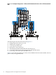
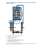
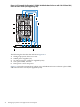
Workgroup System Tower. The control node server blade is installed in device bay 1. If the
enclosure includes a storage blade, the storage blade is installed in device bay 2.
Front of Workgroup System Tower:
UseBayUseBay
Server Blade8Server Blade4
Server Blade7Server Blade3
Server Blade6Storage Blade (SB40c) Or Server Blade2
Server Blade5Control Node/Server Blade1
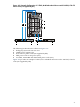
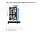
Rear of Workgroup System Tower:
Interconnect Module 2Interconnect Module 1Bay
Not UsedHP GbE2c ModuleUse
Interconnect Module 4Interconnect Module 3Bay
InfiniBand Switch Module (double width)Use
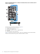
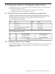
B.2 Workgroup System Tower Fan Bays
If more than half of the device bays are populated (for example, there are more than four server
blades) the enclosure shall be configured with six fans. Otherwise, the enclosure shall be
configured with four fans.
B.1 Workgroup System Tower Device and Interconnect Bay Rules 39