
Microsoft Windows Compute Clusters

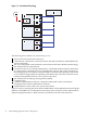
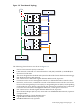

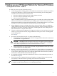


Figure 2-1 Two-Network Topology
9
8
6
5
6
5
6
5
7
7
42
1
3
The following cluster features are shown in Figure 2-1:
1
Site local area network (LAN) connection.
2
LAN network, connected to a network interface card (NIC) installed (or embedded) in the
cluster's head node.
3
The server designated as the head node (control node in HP Cluster Platform terminology).
4
NIC dedicated to the LAN network.
5
Connection to the server's management interface, a dedicated hardware interface that listens
for, and executes commands received via the Ethernet network. This card is also known as
the management processor (MP), or integrated lights-out (iLO) card, depending on the model
of server. Where supported by the operating environment, this connection is used for server
hardware management functions, such as power-off or boot.
6
NIC dedicated to the Message Passing Interface (MPI).
7
Compute nodes.
8
Common Gigabit Ethernet network, used both for MPI traffic, and for in-band job
management, and cluster administrative functions.
9
Gigabit Ethernet switch, used as the system interconnect.
Figure 2-2 shows a topology based on a dedicated MPI fabric. This might be built around Gigabit
Ethernet or InfiniBand. A second Ethernet network provides routing for cluster administrative,
and job management traffic. A third network is provided via the site LAN connection.
14 Understanding Supported Cluster Configurations