
Microsoft Windows Compute Clusters

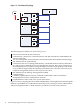
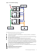

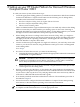


Figure 2-2 Three-Network Topology
1
13
11
12
15
8
8
5
5
7
7
14
6
9
9
10
6
1
2
3
4
6 8
5
The following cluster features are shown in Figure 2-2:
1
Site local area network (LAN) connection.
2
LAN network, connected to a network interface card (NIC) installed (or embedded) in
the cluster's head node.
3
The server designated as the head node (control node in HP Cluster Platform terminology).
4
NIC dedicated to the LAN network.
5
NIC connected to a dedicated Gigabit Ethernet MPI network, if present.
6
Connection to the server's management interface, a dedicated hardware interface that
listens for, and executes, commands received via the Ethernet network. This card is also
known as the management processor (MP), or integrated lights-out (ILO) card, depending
on the model of server. Where supported by the operating environment, this connection
is used for server hardware management functions, such as power-off or boot.
7
NIC connected to a shared Gigabit Ethernet MPI network, if present.
8
Host Channel Adapter (HCA) card, connected to an InfiniBand MPI network, if present.
9
Compute nodes.
10
Ethernet network for cluster administration.
11
Gigabit Ethernet MPI network, if present.
12
InfiniBand MPI network, if present.
2.2 Identifying Supported Topologies 15