Hardware Reference Guide HP Compaq Business Desktops dx6120 Microtower Models Document Part Number: 374967-001 September 2004 This guide provides basic information for upgrading this computer model.
© Copyright 2004 Hewlett-Packard Development Company, L.P. The information contained herein is subject to change without notice. Microsoft, MS-DOS, Windows, and Windows NT are trademarks of Microsoft Corporation in the U.S. and other countries. The only warranties for HP products and services are set forth in the express warranty statements accompanying such products and services. Nothing herein should be construed as constituting an additional warranty.
Contents 1 Product Features Standard Configuration Features. . . . . . . . . . . . . . . . . . . . . . . . . . . . . . . . . . . . . . . . . . Front Panel Components . . . . . . . . . . . . . . . . . . . . . . . . . . . . . . . . . . . . . . . . . . . . . . . . Rear Panel Components . . . . . . . . . . . . . . . . . . . . . . . . . . . . . . . . . . . . . . . . . . . . . . . . Keyboard . . . . . . . . . . . . . . . . . . . . . . . . . . . . . . . . . . . . . . . . . . . . . . . . . . . . . . . . . . . .
Contents A Specifications B Battery Replacement C Security Lock Provisions Installing a Security Lock . . . . . . . . . . . . . . . . . . . . . . . . . . . . . . . . . . . . . . . . . . . . . . . C–1 Cable Lock . . . . . . . . . . . . . . . . . . . . . . . . . . . . . . . . . . . . . . . . . . . . . . . . . . . . . . . C–1 Padlock . . . . . . . . . . . . . . . . . . . . . . . . . . . . . . . . . . . . . . . . . . . . . . . . . . . . . . . . . .
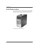
1 Product Features Standard Configuration Features The HP Compaq Microtower features may vary depending on the model. For a complete listing of the hardware and software installed in the computer, run the Diagnostics for Windows utility. Instructions for using this utility are provided in the Troubleshooting Guide on the Documentation CD. Microtower Configuration Hardware Reference Guide www.hp.
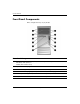
Product Features Front Panel Components Drive configuration may vary by model.
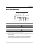
Product Features Rear Panel Components Rear Panel Components 1 Power Cord Connector 7 RJ-45 Network Connector 2 Voltage Select Switch 8 Parallel Connector 3 PS/2 Mouse Connector 9 Monitor Connector 4 a PS/2 Keyboard Connector - Headphone/Line-Out Connector 5 o Universal Serial Bus (USB) q Line-In Audio Connector 6 m w Microphone Connector ✎ Serial Connector Arrangement and number of connectors may vary by model.
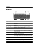
Product Features Keyboard Keyboard Components 1 Function Keys Perform special functions depending on the software application being used. 2 Editing Keys Includes the following: Insert, Home, Page Up, Delete, End, and Page Down. 3 Status Lights Indicate the status of the computer and keyboard settings (Num Lock, Caps Lock, and Scroll Lock). 4 Numeric Keys Work like a calculator keypad. 5 Arrow Keys Used to navigate through a document or Web site.
Product Features Windows Logo Key Use the Windows Logo key in combination with other keys to perform certain functions available in the Windows operating system. Refer to the “Keyboard” section to identify the Windows Logo key. Windows Logo Key Functions Windows Logo Key Displays or hides the Start menu. Windows Logo Key + d Displays the Desktop. Windows Logo Key + m Minimizes all open applications. Shift + Windows Logo Key + m Undoes Minimize All. Windows Logo Key + e Launches My Computer.
Product Features Serial Number Location Each computer has a unique serial number and a product ID number that are located on the top cover of the computer. Keep these numbers available for use when contacting customer service for assistance. Serial Number and Product ID Location 1–6 www.hp.
2 Hardware Upgrades Serviceability Features The Microtower computer includes features that make it easy to upgrade and service. No tools are needed for most of the installation procedures described in this chapter. Warnings and Cautions Before performing upgrades be sure to carefully read all of the applicable instructions, cautions, and warnings in this guide.
Hardware Upgrades Removing the Computer Access Panel To remove the computer access panel: 1. Turn off the computer properly through the operating system and turn off any external devices. 2. Disconnect the power cord from the power outlet and the computer, and disconnect any external devices. Ä CAUTION: Before removing the computer access panel, ensure that the computer is turned off and that the power cord is disconnected from the electrical outlet. 3.
Hardware Upgrades Removing the Front Bezel To remove the front bezel: 1. Turn off the computer properly through the operating system and turn off any external devices. 2. Disconnect the power cord from the power outlet and the computer, and disconnect any external devices. 3. Remove the computer access panel. 4. To remove the front bezel, press down on all three tabs on the left side of the bezel 1 then rotate the bezel off the chassis 2, beginning with the left side then the right side.
Hardware Upgrades Installing Additional Memory The computer comes with double data rate 2 synchronous dynamic random access memory (DDR2-SDRAM) dual inline memory modules (DIMMs). DIMMs The memory sockets on the system board can be populated with up to four industry-standard DIMMs. These memory sockets are populated with at least one preinstalled DIMM. To achieve the maximum memory support, you can populate the system board with up to 4GB of memory configured in a high-performing dual channel mode.
Hardware Upgrades Populating DIMM Sockets The system will automatically operate in single channel mode, dual channel Asymmetric mode, or a higher-performing dual channel Interleaved mode, depending on how the DIMMs are installed. ■ The system will operate in single channel mode if the DIMM sockets are populated in one channel only.
Hardware Upgrades DIMM Socket Locations 2–6 Item Description Socket Color 1 DIMM socket XMM1, Channel A White 2 DIMM socket XMM2, Channel A Black 3 DIMM socket XMM3, Channel B White 4 DIMM socket XMM4, Channel B Black www.hp.
Hardware Upgrades Installing DIMMs Ä CAUTION: The memory module sockets have gold metal contacts. When upgrading the memory, it is important to use memory modules with gold metal contacts to prevent corrosion and/or oxidation resulting from having incompatible metals in contact with each other. Ä CAUTION: Static electricity can damage the electronic components of the computer or optional cards.
Hardware Upgrades 5. Open both latches of the memory module socket 1, and insert the memory module into the socket 2. Installing a DIMM module can be installed in only one way. Match the notch ✎ Aonmemory the module with the tab on the memory socket. maximum performance, poplulate the sockets so that the memory ✎ For capacity of Channel A is equal to the memory capacity of Channel B.
Hardware Upgrades Replacing or Upgrading a Drive The computer supports up to six drives that may be installed in various configurations. This section describes the procedure for replacing or upgrading the storage drives. A Torx screwdriver is needed to replace the guide screws on a drive. Ä CAUTION: Make sure you back up your personal files on the hard drive to an external storage device, such as a CD, before removing the hard drive. Failure to do so will result in data loss.
Hardware Upgrades Removing a Drive 1. Turn off the computer properly through the operating system and turn off any external devices. Disconnect the power cord from the power outlet and disconnect any external devices. 2. Remove the access panel and front bezel. 3. Disconnect the power and data cables from the back of the drive, as indicated in the following illustrations. Disconnecting the Optical Drive Cables 2–10 www.hp.
Hardware Upgrades Disconnecting the Diskette Drive Cables Disconnecting the Hard Drive Cables Hardware Reference Guide www.hp.
Hardware Upgrades 4. A latch drive bracket with release tabs secures the drives in the drive bay. Lift the release tab on the latch drive bracket 1 for the drive you want to remove, then slide the drive from its drive bay 2. Removing the Drives 5. Remove the four guide screws (two on each side) from the old drive. You will need these screws to install a new drive. 2–12 www.hp.
Hardware Upgrades Replacing a Drive Ä■ CAUTION: To prevent loss of work and damage to the computer or drive: If you are inserting or removing a hard drive, shut down the operating system properly, then turn off the computer. Do not remove a hard drive while the computer is on or in standby mode. ■ Before handling a drive, ensure that you are discharged of static electricity. While handling a drive, avoid touching the connector.
Hardware Upgrades 2. Slide the drive into the drive bay, making sure to align the guide screws with the guide slots, until the drive snaps into place. Sliding the Drives into the Drive Cage 2–14 www.hp.
Hardware Upgrades 3. Reconnect the power and data cables to the drive as indicated in the following illustrations. Reconnecting the Optical Drive Cables Hardware Reference Guide www.hp.
Hardware Upgrades Reconnecting the Diskette Drive Cables Reconnecting the Hard Drive Cables 2–16 www.hp.
Hardware Upgrades 4. If installing a new hard drive, connect the data cable to the system board. replacement hard drive kit includes several data cables. Make ✎ The sure to use the cable that is exactly the same as the factory-installed cable. has only one SATA hard drive, you must connect the ✎ Ifhardyourdrivesystem data cable to the connector labeled P60 SATA 0 to avoid any hard drive performance problems.
Hardware Upgrades Removing or Installing an Expansion Card The computer has two PCI expansion slots that can accommodate an expansion card up to 17.46 cm (6.875 inches) in length. The computer also has one PCI Express x1 expansion slot and one PCI Express x16 expansion slot.
Hardware Upgrades To remove, replace, or add an expansion card. 1. Turn off the computer properly through the operating system and turn off any external devices. Disconnect the power cord from the power outlet and disconnect any external devices. 2. Remove the access panel and lay the computer on its side with the opening to internal parts where the access panel was located facing up. 3.
Hardware Upgrades 4. Before installing an expansion card, remove the expansion slot cover or the existing expansion card. a. If you are installing an expansion card in a vacant socket, remove the appropriate expansion slot cover on the back of the chassis. Pull the slot cover straight up from the socket then away from the inside of the chassis. Removing an Expansion Slot Cover 2–20 www.hp.
Hardware Upgrades b. If removing a standard PCI expansion card, hold the card at each end, and carefully rock it back and forth until the connectors pull free from the socket. Pull the expansion card straight up from the socket 1 then away from the inside of the chassis 2 to release it from the chassis frame. Be sure not to scrape the card against the other components. Removing an Expansion Card Hardware Reference Guide www.hp.
Hardware Upgrades c. If removing a PCI Express card, pull the retention arm on the back of the expansion socket away from the card and carefully rock the card back and forth until the connectors pull free from the socket. Pull the expansion card straight up from the socket then away from the inside of the chassis to release it from the chassis frame. Be sure not to scrape the card against the other components.
Hardware Upgrades 6. If replacing or adding a new expansion card, hold the card just above the expansion slot on the system board then move the card toward the rear of the chassis 1 so that the bracket on the card is aligned with the open slot on the rear of the chassis. Gently press the card straight down into the expansion slot on the system board 2.
Hardware Upgrades 8. While holding the expansion card bracket against the chassis, slide the slot cover lock down toward the expansion card brackets and slot covers 1 to secure them in place and replace the screw 2 that secures the slot cover lock. Securing the Expansion Cards and Slot Covers 9. Complete the procedure described in the “Reassembling the Computer” section of this chapter. 2–24 www.hp.
Hardware Upgrades Reassembling the Computer 1. Position the chassis in the upright position. Insert the three hooks on the right side of the bezel 1 into the rectangular holes on the chassis then rotate the bezel into place 2 so that the three tabs on the left side of the bezel snap into the slots on the chassis. Replacing the Front Bezel Hardware Reference Guide www.hp.
Hardware Upgrades 2. Place the side access panel in the proper position on the chassis and slide it into place 1. Ensure that the hole for the thumbscrew is aligned with the hole in the chassis and tighten the thumbscrew 2. Replacing the Side Access Panel 3. Reconnect the power cable to the computer and plug the cable into an electrical outlet. 4. Reconnect all peripheral devices to the computer.
A Specifications HP Compaq Microtower Microtower Dimensions Height Width Depth (depth will increase if the computer is equipped with a port security bracket) Approximate Weight 14.5 in 6.88 in 16.5 in 36.8 cm 17.5 cm 42.0 cm 23.8 lb 10.
Specifications HP Compaq Microtower (Continued) Input Voltage 115 V 230 V 90-132 VAC 100-127 VAC 50-60 Hz 180-264 VAC 200-240 VAC 50-60 Hz 300 W 300 W 8A @ 100 VAC 4A @ 200 VAC Power Supply Operating Voltage Range* Rated Voltage Range Rated Line Frequency Power Output Rated Input Current (maximum)* *This system utilizes a passive power factor corrected power supply. The power factor correction is present in the 230V operating mode only.
B Battery Replacement The battery that comes with the computer provides power to the real-time clock. When replacing the battery, use a battery equivalent to the battery originally installed in the computer. The computer comes with a 3-volt lithium coin cell battery. lifetime of the lithium battery can be extended by plugging the ✎ The computer into a live AC wall socket. The lithium battery is only used when the computer is NOT connected to AC power.
Battery Replacement Ä CAUTION: Static electricity can damage the electronic components of the computer or optional equipment. Before beginning these procedures, ensure that you are discharged of static electricity by briefly touching a grounded metal object. 1. Turn off the computer properly through the operating system, then turn off any external devices. 2. Disconnect the power cord from the power outlet and disconnect any external devices. Then remove the computer access panel.
Battery Replacement Type 2 a. To release the battery from its holder, squeeze the metal clamp that extends above one edge of the battery. When the battery pops up, lift it out 1. b. To insert the new battery, slide one edge of the replacement battery under the holder’s lip with the positive side up. Push the other edge down until the clamp snaps over the other edge of the battery 2. Removing and Replacing a Coin Cell Battery (Type 2) Hardware Reference Guide www.hp.
Battery Replacement Type 3 a. Pull back on the clip 1 that is holding the battery in place, and remove the battery 2. b. Insert the new battery and position the clip back into place. Removing a Coin Cell Battery (Type 3) the battery has been replaced, use the following steps to ✎ After complete this procedure. 5. Replace the computer access panel. 6. Plug in the computer and turn on power to the computer. 7. Reset the date and time, your passwords, and any special system setups, using Computer Setup.
C Security Lock Provisions Installing a Security Lock The security locks displayed below and on the following page can be used to secure the Microtower computer. port security bracket (not shown) is also available. Go to ✎ Awww.hp.com for more information. Cable Lock Installing a Cable Lock Hardware Reference Guide www.hp.
Security Lock Provisions Padlock I Installing a Padlock C–2 www.hp.
D Electrostatic Discharge A discharge of static electricity from a finger or other conductor may damage system boards or other static-sensitive devices. This type of damage may reduce the life expectancy of the device. Preventing Electrostatic Damage To prevent electrostatic damage, observe the following precautions: ■ Avoid hand contact by transporting and storing products in static-safe containers. ■ Keep electrostatic-sensitive parts in their containers until they arrive at static-free workstations.
Electrostatic Discharge ■ Use heelstraps, toestraps, or bootstraps at standing workstations. Wear the straps on both feet when standing on conductive floors or dissipating floor mats. ■ Use conductive field service tools. ■ Use a portable field service kit with a folding static-dissipating work mat. If you do not have any of the suggested equipment for proper grounding, contact an HP authorized dealer, reseller, or service provider.
E Routine Computer Care and Shipping Preparation Routine Computer Care Follow these suggestions to take care of the computer and monitor: Hardware Reference Guide ■ Operate the computer on a sturdy, level surface. Leave a 10.2-cm (4-inch) clearance at the back of the system unit and above the monitor to permit the required airflow. ■ Never operate the computer with the cover or side panel removed. ■ Never restrict the airflow into the computer by blocking the front vents or air intake.
Routine Computer Care and Shipping Preparation Optical Drive Precautions Be sure to observe the following guidelines while operating or cleaning the optical drive. Operation ■ Do not move the drive during operation. This may cause it to malfunction during reading. ■ Avoid exposing the drive to sudden changes in temperature, as condensation may form inside the unit. If the temperature suddenly changes while the drive is on, wait at least one hour before you turn off the power.
Routine Computer Care and Shipping Preparation Shipping Preparation Follow these suggestions when preparing to ship the computer: 1. Back up the hard drive files on PD discs, tape cartridges, CDs, or diskettes. Be sure that the backup media is not exposed to electrical or magnetic impulses while stored or in transit. hard drive locks automatically when the system power is ✎ The turned off. 2. Remove and store any program diskettes from the diskette drives. 3.
Routine Computer Care and Shipping Preparation E–4 www.hp.
Index A access panel removing 2–2 replacing 2–26 application key 1–4 audio connector 1–3 B backup files 2–9, 2–17 battery replacement B–1 C CD-R/RW drive installing 2–9 locating 2–9 CD-ROM drive installing 2–9 locating 2–9 components front panel 1–2 keyboard 1–4 rear panel 1–3 computer routine care E–1 security locks C–1 shipping preparation E–3 specifications A–1 D diskette drive activity light 1–2 eject button 1–2 Hardware Reference Guide installing 2–9 locating 2–9 drive positions 2–9 DVD+R/RW drive
Index expansion card 2–18 memory 2–4 K keyboard components 1–4 connector 1–3 L locks cable lock C–1 padlock C–2 M memory Asymetric mode 2–5 capacity 2–4, 2–5, 2–8 identifying sockets 2–5 installing 2–4 Interleaved mode 2–5 populating sockets 2–5 single channel mode 2–5 specifications 2–4 microphone connector 1–2, 1–3 monitor, connecting 1–3 mouse connector 1–3 special functions 1–5 O optical drives activity light 1–2 defined 1–2 eject button 1–2 installing 2–13 locating 2–9 removing 2–10 P parallel co