
HP Matrix infrastructure orchestration: ESXi OS Deployment

Technical white paper: ESXi OS Deployment
14
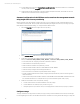
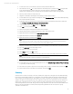
2. Select the ESXi host, select the
Configuration
tab, and then under Hardware select
Networking
.
• For virtual switch vSwitch0, Service Console and Physical Adapter vmnic0 should be displayed.
• For virtual switch vSwitch1, Service Console 2 and Physical Adapter vmnic1 should be displayed.
If not, click Refresh.
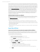
3. Select
Properties
for vSwitch0, select
VM Network
, and then click
Edit
.
4. Specify the Network Label (in this example, deployment), click
OK
, and then click
Close
.
5. Select
Properties
for vSwitch1, select the
Network Adapters
tab, and then click
Add
.
6. From the Unclaimed Adapters list, select the other adapter that is associated with the management network (in
this example, the adapter is vmnic2), and then click
Next
.
7. Confirm the order of the adapters, and then click
Next
.
8. Review the summary, and then click
Finish
.
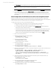
9. Select the
Ports
tab, and then click
Add
.
10. Select
Virtual Machine
for the Connection Type, and then click
Next
.
11. Specify the Network Label (in this example, mgmt_A), and then click
Next
.
Note
The Network Label specified must match the name of the primary Virtual Connect network, so that infrastructure
orchestration will recognize the network as a single Virtual and Physical network.
12. Confirm the preview, and then click
Finish.
Note
For each virtual switch, configure the switch options as needed to meet customer or site-specific requirements.
For example, optionally, select the
vSwitch
in the vSwitch Properties screen, click
Edit
, select the
NIC Teaming
tab,
and then configure load balancing and failover policies to determine how network traffic is distributed between
adapters and how to reroute traffic in the event of an adapter failure. The Network Label specified must match the
name of the primary Virtual network.
13. Click
Close.
14. Click
Add Networking.
15. Select
VMKernel
for the Connection Type, and then click
Next.
16. Select
Create a virtual switch
, select the adapters that are associated with the vMotion network (in this example,
the adapters are vmnic3 and vmnic4), and then click
Next
.
17. Specify the Network Label (in this example, vMotion), and then click
Next
.
18. Specify the IP Address and Subnet Mask, and then click
Next
.
19. Confirm the preview, and then click
Finish
.
20. Click
Add Networking
.
21. Select
Virtual Machine
for the Connection Type, and then click
Next
.
22. Select
Create a virtual switch
, select the adapters that are associated with the production network (in this
example, the adapters are vmnic5 and vmnic6), and then click
Next
.
23. Specify the Network Label (in this example, VLAN 2000), specify the VLAN ID (in this example, 2000), and then
click
Next
.
24. Confirm the preview, and then click
Finish
.
25. For each additional VLAN the ESX host will support (in this example, 2042, 2309, 2740, and 2936), repeat
steps 20-24 above, selecting
Use vSwitch3
in step 22 instead of creating a new virtual switch.
26. Configure the ESX host to access any required storage, using the standard VMware ESX procedures