
HP Matrix infrastructure orchestration: ESXi OS Deployment

Technical white paper: ESXi OS Deployment
4
d. After the above steps have been completed, move the physical server out of the IO Maintenance Server
Pool into the Server Pool where it originally resided before the deletion request.
Important
If the host is the last remaining host in a cluster, manually erase the disk. Do not run an erase disk job when
other hosts remain in the cluster, as
the erase disk job will erase the shared disks
, and data loss will occur.
Verify pre-requisites are met
Before using this guide, verify that all pre-requisites are met. The HP Matrix Operating Environment (Matrix OE) must be
installed and operational. In this example, Matrix OE version 7.3 Update 1 is used. VMware vCenter Server must be installed
on a server other than the Central Management Server (CMS) or the deployment server, and must be operational. The
vSphere Client must be installed and operational to access the vCenter Server. In this example, vCenter Server 5.5 and
vSphere Client 5.5 are used.
In this example, Virtual Connect Flex-10 Ethernet modules are installed in Bays 1 and 2. A single external network switch
(a ProCurve Switch 3500yl-24G) is used. Optionally, two external network switches could be used for high availability.
The Virtual Connect Flex-10 Ethernet modules are configured as in scenario 2:4, Flex-10 - VLAN Tagging (802.1Q) with
Multiple Shared Uplink Sets (SUS) and Tunneled VLANs - ESX 4, in the HP Virtual Connect Ethernet Cookbook: Single and Multi
Enclosure Domain (Stacked) Scenarios
(http://h20000.www2.hp.com/bc/docs/support/SupportManual/c01990371/c01990371.pdf
). Two shared uplink sets,
which are presented to the server as separate networks, are defined to carry deployment, ESX console and ESX vMotion
traffic. Additionally two vNet networks are defined to carry the multiple VLAN traffic of production networks that will be
configured in ESX to be presented to virtual machine
Two Shared Uplink Sets are defined:
• Bay 1, Port X1, and associated networks deployment, mgmt_A, and vMotion_A, are added to the first Shared Uplink Set
(in this example, VLAN-Trunk-1)
• Bay 2, Port X1, and associated networks mgmt_B and vMotion_B, are added to the second Shared Uplink Set (in this
example, VLAN-Trunk-2)
Two vNet Ethernet Networks are defined, with VLAN tunneling enabled:
• Bay 1, Port X2 is added to the first vNet (in this example, prod_A)
• Bay 2, Port X2 is added to the second vNet (in this example, prod_B)
The corresponding ports in the external network switches are configured to support the appropriate VLAN IDs (in this
example, 101, 102, and 103) for the Shared Uplink Set associated networks (in this example, deployment, mgmt_A,
mgmt_B, vMotion_A, and vMotion_B) and the VLANs of the production networks of the vNets (in this example, 2000, 2042,
2309, 2740, and 2936).
Note
Optionally, additional networks may also be configured, such as a heartbeat network to provide high availability for the
VMware vCenter Server or iSCSI connections
1
.
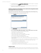
The Virtual Connect configuration used in this example is summarized in the following tables. Table 1 summarizes the
ethernet network configuration.
1
1 In the HP Matrix Operating Environment, iSCSI is supported as virtual machine guest storage. For more information, refer to the Insight Management Support
Matrix (www.hp.com/go/matrixoe/docs) or the CloudSystem Matrix Compatibility Chart (www.hp.com/go/matrixcompatibility).