
HP Installation Guide, HP AT094A PCIe 2P 8Gb FC and 2P 1/10GbE Adapter, Edition 2


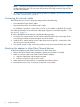

NOTE: The two ports closest to the PCIe edge connector (bottom two as in Figure 1 (page 5))
are the Networking ports. The two ports away from the PCIe edge connector (top two) are
the Fibre Channel ports.
5. Do not power on the system until the following section is complete: “Attaching the adapter to
other Fibre Channel devices” (page 8)
Connecting the network cables
The AT094A has two LC ports. These ports support either of the following:
• Direct Attached Copper (DAC) cables.
• Optical Modules to be used with fiber optic cables.
• For 1000Base-T operation, connect Cat5, Cat 5E, or Cat6 cables via the RJ45 SFP module.
See Cable specifications for the maximum cable length supported, in the following table: “Cable
specifications” (page 15)
To connect the AT094A to the network, complete the following steps:
1. Orient the SFP+ optical module or DAC cable so that the Gold Fingers on the edge of the
circuit board is located closest to the option card circuit board.
2. Install the SFP+ optical module or DAC cable all the way into the SFP+ socket until it clicks
into place and is securely latched.
3. If an optical module is used, remove the protective cover and connect the fiber optic cable.
Attaching the adapter to other Fibre Channel devices
To attach the adapter to other Fibre Channel devices, follow these steps:
1. Remove the Fibre Channel host bus adapter’s optical port protector (if included).
2. Attach a connector cable to the Fibre Channel host bus adapter.
a. Align the slotted plug with the keyed connector.
b. Push the connector in until you hear it click.
3. Attach the free end of the cable to a compatible Fibre Channel device.
4. Reconnect the power cord, if necessary, and power on the system.
8 Installing an adapter