HP StorageWorks D2200sb PCIe Storage Blade User Guide Abstract This document is for the person who installs, administers, and troubleshoots servers and storage systems. HP assumes you are qualified in the servicing of computer equipment and trained in recognizing hazards in products with hazardous energy levels.
© Copyright 2010, 2012 Hewlett-Packard Development Company, L.P. The information contained herein is subject to change without notice. The only warranties for HP products and services are set forth in the express warranty statements accompanying such products and services. Nothing herein should be construed as constituting an additional warranty. HP shall not be liable for technical or editorial errors or omissions contained herein. Microsoft is a U.S. registered trademark of Microsoft Corporation.
Contents Component identification ............................................................................................................... 5 Front panel components ............................................................................................................................. 5 Front panel LEDs ....................................................................................................................................... 6 SAS and SATA hard drive bay numbers ......................
Is the storage blade operating properly? .......................................................................................... 27 Recognizing hard drive failure .................................................................................................................. 28 Effects of a hard drive failure .......................................................................................................... 28 Compromised fault tolerance ..........................................................
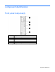
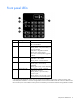
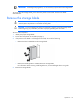
Component identification Front panel components Item Description 1 Product information tag 2 LED panel 3 Drive drawer release latch 4 Drive drawer handle Storage blade locking lever* 5 * Removing the storage blade from the enclosure removes power from the drives.
Front panel LEDs Item Description Status 1 UID LED Blue = Identified Off = Not identified 2 System health LED* Green = Normal operation Flashing amber = No partner blade, or not yet recognized Solid amber = Degraded condition Flashing red = System critical Red = Drive over-temperature triggered shutdown 3 Drive fault LED Off = Normal operation Solid amber = Drive failed Flashing amber = Predictive failure 4 Drive activity LED Solid green = Drive installed Flashing green = Drive activity estab
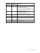
SAS and SATA hard drive bay numbers SAS and SATA hard drive LEDs Item Description 1 Fault/UID LED (amber/blue) 2 Online LED (green) SAS and SATA hard drive LED combinations Online/activity LED (green) Fault/UID LED (amber/blue) Interpretation On, off, or flashing Alternating amber and blue The drive has failed, or a predictive failure alert has been received for this drive; it also has been selected by a management application.
Online/activity LED (green) Fault/UID LED (amber/blue) Interpretation On Off The drive is online, but it is not active currently. Flashing regularly (1 Hz) Amber, flashing regularly (1 Hz) Do not remove the drive. Removing a drive may terminate the current operation and cause data loss. The drive is part of an array that is undergoing capacity expansion or stripe migration, but a predictive failure alert has been received for this drive.
Operations Important Safety Information Before installing this product, read the Important Safety Information document provided. Power down the partner server blade In systems that use the storage blade as external data storage, be sure that the partner server blade is the first unit to be powered down and the last to be powered back up. Taking this precaution ensures that the system and the OS are shut down in an orderly manner.
IMPORTANT: If installing a hot-plug device, it is not necessary to power down the storage blade. To power down the storage blade, power down the partner server blade. See the server blade documentation. Remove the storage blade WARNING: To reduce the risk of personal injury from hot surfaces, allow the drives and the internal system components to cool before touching them. CAUTION: To prevent damage to electrical components, properly ground the storage blade before beginning any installation procedure.
5. o Partnered with a half-height server blade o Partnered with a full-height server blade Place the storage blade on a flat, level work surface. Remove the access panel WARNING: To reduce the risk of personal injury from hot surfaces, allow the drives and the internal system components to cool before touching them. CAUTION: To prevent damage to electrical components, properly ground the server blade before beginning any installation procedure. Improper grounding can cause ESD.
To remove the component: 1. Power down the partner server blade (on page 9). 2. Remove the storage blade (on page 10). 3. Press the access panel release button. 4. Slide the access panel toward the rear of the storage blade. 5. Remove the access panel. Install the access panel WARNING: To reduce the risk of personal injury from hot surfaces, allow the drives and the internal system components to cool before touching them.
Setup Kit contents When unpacking the HP StorageWorks D2200sb PCIe storage blade, locate the following items: • HP StorageWorks D2200sb PCIe storage blade • Half-height blade shelf • Documentation kit Installing an HP BladeSystem c-Class enclosure Before performing any procedures specific to the storage blade, install an HP BladeSystem c-Class enclosure. The most current documentation for HP BladeSystem components is available at the HP Business Support Center website (http://www.hp.
Installation guidelines When installing the storage blade, observe the following guidelines: • Install hard drives in the storage blade before installing the storage blade in the enclosure. • Be sure that the partner server blade is powered down before installing the storage blade. Onboard Administrator is used to configure the enclosure and the storage blade. To function with the storage blade, Onboard Administrator version 3.10 or later is required.
Installing a storage blade CAUTION: To prevent improper cooling and thermal damage, do not operate the storage blade or the enclosure unless the first drive bay is populated with a drive, and drive bays 2 and 3 and all device bays are populated with either a component or a blank. CAUTION: Thermal regulation is maintained only when the drive drawer is closed.
o To install the storage blade with a full-height server blade, install the half-height blade shelf. If installing two storage blades with one partner server blade, install the second storage blade in the bay directly above the first one. If installing two storage blades with one partner server blade in an HP BladeSystem c3000 Enclosure, use the mini divider instead of the half-height blade shelf. For more information, see the HP BladeSystem c3000 Enclosure Quick Setup Instructions. 4.
o Partnered with a half-height server blade o Partnered with a full-height server blade o Partnered with a full-height server blade and an additional storage blade IMPORTANT: Most full-height server blades connect to one or two storage blades through a PCI Express Mezzanine card installed in the server. For server-specific information, see the storage blade QuickSpecs.
6. Install a server blade. See the documentation that ships with the server blade. 7. Configure the storage blade ("Configuration tools" on page 23). Hard drives The storage blade supports up to 12 SAS or 12 SATA hard drives. Always populate hard drive bays starting with the lowest hard drive bay number ("SAS and SATA hard drive bay numbers" on page 7).
are not fully protected by system air flow. • A fast beep and flash (2 per second)—To avoid drive damage or data loss and storage blade shutdown, close the drive drawer immediately. When the drives reach critical temperatures, the system shuts down. 1. Open the hard drive drawer. 2. Remove the hard drive blank.
3. Prepare the hard drive. 4. Install the hard drive. 5. Install the storage blade in the enclosure. 6. Power up the partner server blade. See the server blade documentation. 7. Determine the status of the drive from the hot-plug SAS or SATA drive LED combinations ("SAS and SATA hard drive LED combinations" on page 7). 8. Configure the storage blade ("Configuration tools" on page 23). Flash-backed write cache (FBWC) option FBWC consists of a cache module and a capacitor pack.
WARNING: To reduce the risk of personal injury from hot surfaces, allow the drives and the internal system components to cool before touching them. CAUTION: To prevent damage to electrical components, properly ground the server blade before beginning any installation procedure. Improper grounding can cause ESD. To install the component: 1. Back up all data on the storage blade. 2. Power down the partner server blade. For more information, see the server blade documentation. 3.
7. Install the FBWC module. To avoid possible damage to the storage blade, be sure that the module is fully seated before installing the screw. 8. Install the FBWC capacitor pack. 9. Close the hard drive drawer. 10. Install the access panel (on page 12). 11. Install the storage blade in the enclosure. 12. Power up the partner server blade. See the server blade documentation. The capacitor pack is fully charged in approximately 5 minutes.
Configuration and utilities Configuration tools Array Configuration Utility ACU is a browser-based utility with the following features: • Runs as a local application or remote service • Supports online array capacity expansion, logical drive extension, assignment of online spares, and RAID or stripe size migration • Suggests the optimum configuration for an unconfigured system • Provides different operating modes, enabling faster configuration or greater control over the configuration options • Re
• Setting the controller to be the boot controller • Selecting the boot volume If you do not use the utility, ORCA will default to the standard configuration. For more information regarding the default configurations that ORCA uses, see the HP ROM-Based Setup Utility User Guide on the Documentation CD. For more information about the controller and its features, see the HP Smart Array Controllers for HP ProLiant Servers User Guide on the HP website (http://bizsupport2.austin.hp.
Remote support and analysis tools HP Insight Remote Support software HP strongly recommends that you install HP Insight Remote Support software to complete the installation or upgrade of your product and to enable enhanced delivery of your HP Warranty, HP Care Pack Service, or HP contractual support agreement.
• The most recent version of a particular server blade or option firmware from the HP website (http://www.hp.com/support) • Components for option firmware updates available from the HP website (http://www.hp.com/support) Running the SmartStart CD also provides updated firmware. HP offers a subscription service that can provide notification of firmware updates. For more information, see "Subscriber's Choice (on page 26).
Troubleshooting If the storage blade does not power up If the storage blade does not start: 1. Be sure that the storage blade is installed adjacent to the partner server blade. 2. Use the Onboard Administrator to be sure that sufficient power is available. 3. Use the Onboard Administrator to verify that sufficient cooling is available. 4. Restart the partner server blade. IMPORTANT: If the system does not restart, proceed to "Diagnostic Questions (on page 27)." 5.
Answer Possible reasons Possible solutions LED ("Front panel LEDs" on page 6) indicates normal temperature. The hard drive drawer was open too long and Restart the partner server blade. triggered critical overtemperature alerts. Recognizing hard drive failure A steadily illuminated Fault LED on a hard drive indicates that the drive has failed. Other indications of failed hard drives: • ACU represents failed drives with a distinctive icon. • HP SIM can detect failed drives remotely across a network.
For example, fault tolerance might occur when a drive in an array fails while another drive in the array is being rebuilt. Compromised fault tolerance can also be caused by problems unrelated to drives. In such cases, replacing the physical drives is not required. Recovering from compromised fault tolerance If fault tolerance is compromised, inserting replacement drives does not improve the condition of the logical volume. Perform the following procedure to recover data: 1.
o In RAID 1+0 configurations, any drives that are not mirrored to other removed or failed drives can be simultaneously replaced offline without data loss. Automatic data recovery (rebuild) When you replace a hard drive in an array, the controller uses the fault-tolerance information on the remaining drives in the array to reconstruct the missing data (the data that was originally on the replaced drive) and write it to the replacement drive. This process is called automatic data recovery, or rebuild.
If this situation occurs, reboot the server. The system may temporarily become operational long enough to allow recovery of unsaved data. In any case, locate the faulty drive, replace it, and restore data from backup. Drive failure in a NetWare environment Use CPQONLIN to identify and monitor drive failure status in a NetWare environment. For more information, see Configuring Arrays on HP Smart Array Controllers on the HP website (http://bizsupport1.austin.hp.
Some status messages are available without pressing the F3 key. For example, on the Main menu, the FAILED status appears next to the logical drive that has failed. EXPANDING and REBUILDING appear next to the array in which the activity is occurring. Handling disk drive failures If the storage blade was configured with hardware fault tolerance, complete the following steps after a disk drive failure: 1. Determine which physical drive failed. On hot-plug drives, an amber drive failure LED illuminates. 2.
Regulatory compliance notices Regulatory compliance identification numbers For the purpose of regulatory compliance certifications and identification, this product has been assigned a unique regulatory model number. The regulatory model number can be found on the product nameplate label, along with all required approval markings and information. When requesting compliance information for this product, always refer to this regulatory model number.
Disposal of waste equipment by users in private households in the European Union This symbol on the product or on its packaging indicates that this product must not be disposed of with your other household waste. Instead, it is your responsibility to dispose of your waste equipment by handing it over to a designated collection point for the recycling of waste electrical and electronic equipment.
Electrostatic discharge Preventing electrostatic discharge To prevent damaging the system, be aware of the precautions you need to follow when setting up the system or handling parts. A discharge of static electricity from a finger or other conductor may damage system boards or other static-sensitive devices. This type of damage may reduce the life expectancy of the device. To prevent electrostatic damage: • Avoid hand contact by transporting and storing products in static-safe containers.
Specifications Environmental specifications Specification Value Temperature range* Operating 10°C to 35°C (50°F to 95°F) Maximum rate of change is 10º C/hr (50º F/hr) Storage -30°C to 60°C (-22°F to 140°F) Maximum rate of change is 20º C/hr (68º F/hr) Relative humidity** Operating 20% to 80% relative humidity (Rh), 28º C (82.4º F) maximum wet bulb temperature, non-condensing Storage 5% to 90% relative humidity (Rh), 38.7º C (101.
Support and other resources Before you contact HP Be sure to have the following information available before you call HP: • Active Health System log Download and have available an Active Health System log for 3 days before the failure was detected. For more information, see the HP iLO 4 User Guide or HP Intelligent Provisioning User Guide on the HP website (http://www.hp.com/go/ilo/docs).
providers or service partners) identifies that the repair can be accomplished by the use of a CSR part, HP will ship that part directly to you for replacement. There are two categories of CSR parts: • Mandatory—Parts for which customer self repair is mandatory. If you request HP to replace these parts, you will be charged for the travel and labor costs of this service. • Optional—Parts for which customer self repair is optional. These parts are also designed for customer self repair.
Pour plus d'informations sur le programme CSR de HP, contactez votre Mainteneur Agrée local. Pour plus d'informations sur ce programme en Amérique du Nord, consultez le site Web HP (http://www.hp.com/go/selfrepair). Riparazione da parte del cliente Per abbreviare i tempi di riparazione e garantire una maggiore flessibilità nella sostituzione di parti difettose, i prodotti HP sono realizzati con numerosi componenti che possono essere riparati direttamente dal cliente (CSR, Customer Self Repair).
HINWEIS: Einige Teile sind nicht für Customer Self Repair ausgelegt. Um den Garantieanspruch des Kunden zu erfüllen, muss das Teil von einem HP Servicepartner ersetzt werden. Im illustrierten Teilekatalog sind diese Teile mit „No“ bzw. „Nein“ gekennzeichnet. CSR-Teile werden abhängig von der Verfügbarkeit und vom Lieferziel am folgenden Geschäftstag geliefert. Für bestimmte Standorte ist eine Lieferung am selben Tag oder innerhalb von vier Stunden gegen einen Aufpreis verfügbar.
sustituciones que lleve a cabo el cliente, HP se hará cargo de todos los gastos de envío y devolución de componentes y escogerá la empresa de transporte que se utilice para dicho servicio. Para obtener más información acerca del programa de Reparaciones del propio cliente de HP, póngase en contacto con su proveedor de servicios local. Si está interesado en el programa para Norteamérica, visite la página web de HP siguiente (http://www.hp.com/go/selfrepair).
Opcional – Peças cujo reparo feito pelo cliente é opcional. Essas peças também são projetadas para o reparo feito pelo cliente. No entanto, se desejar que a HP as substitua, pode haver ou não a cobrança de taxa adicional, dependendo do tipo de serviço de garantia destinado ao produto. OBSERVAÇÃO: Algumas peças da HP não são projetadas para o reparo feito pelo cliente. A fim de cumprir a garantia do cliente, a HP exige que um técnico autorizado substitua a peça.
Support and other resources 43
Support and other resources 44
Acronyms and abbreviations ACU Array Configuration Utility ADU Array Diagnostics Utility CPQONLIN NetWare Online Array Configuration Utility CSR Customer Self Repair FC Fibre Channel ISEE Instant Support Enterprise Edition ORCA Option ROM Configuration for Arrays OSEM Open Services Event Manager PSP ProLiant Support Pack SAS serial attached SCSI SATA serial ATA SIM Systems Insight Manager Acronyms and abbreviations 45
UID unit identification Acronyms and abbreviations 46
Documentation feedback HP is committed to providing documentation that meets your needs. To help us improve the documentation, send any errors, suggestions, or comments to Documentation Feedback (mailto:docsfeedback@hp.com). Include the document title and part number, version number, or the URL when submitting your feedback.
Index A F access panel 11 acoustics statement for Germany 36 ACU (Array Configuration Utility) 24 additional guidelines for installation with a full-height partner server blade 15 additional guidelines for installation with a half-height partner server blade 14 ADU (Array Diagnostic Utility) 26 automatic data recovery (rebuild) 31 factors to consider before replacing hard drives 30 failed drives or interim recovery mode 32 failure of another drive during rebuild 32 features 5 firmware update 27 flash-bac
L T LED, health 6 LED, internal health 6 LEDs, hard drive 7, 8 technical support 39, 40 telephone numbers 39, 40 time required for a rebuild 31 troubleshooting 28 M Management Agents 25 management tools 25 U UID LED 6 O operations 9 ORCA (Option ROM Configuration for Arrays) 24 P phone numbers 39 powering down 9, 10 powering up 9 preparation procedures 9 problem diagnosis 28 R recovering from compromised fault tolerance 30 regulatory compliance notices 34, 35 removing the access panel 11 removing th