
HP BladeSystem Deployment Guide for Solutions with 6Gb SAS BL Switches and External SAS Storage Enclosures


Troubleshooting
When troubleshooting issues with a device in your HP BladeSystem solution, keep in mind that the
device is part of a solution, so correcting the issue may require a fair amount of analysis. Before
contacting HP, gather information about the device, the solution, and the issue. When contacting
HP, be sure to inform support personnel that the device is part of a BladeSystem solution.
Gathering troubleshooting information
Before contacting HP support, do the following:
• Examine LEDs on all solution devices.
• Follow and ensure integrity of all cabling paths.
• Obtain System Event Logs from software tools, such as Onboard Administrator and Virtual
SAS Manager.
• Obtain the ADU Report.
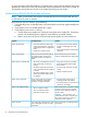
Troubleshooting the HP 6Gb SAS BL Switch
SolutionProblem
Amber LED on Switch
• Check OA and VSM for status alerts to identify the
problem.
• See the HP 6Gb SAS BL Switch User Guide for LED
definitions.
Verify the power up sequence and allow sufficient time for
each component to power up. Verify cabling from the
Storage not ready during POST (blade) OR Controller
lockup during POST
switch to the storage enclosures. For more information
about power-up sequence, see “Installation best practices
and procedures” (page 52). For more information about
cabling, see “Deployment examples” (page 71).
Verify the power up sequence and allow sufficient time for
each component to power up.
VSM application is not accessible
Verify that the P711m, 712m, or P721m/P731m SAS
controller is installed in the correct server expansion slot.
Unable to access the storage
The switch must be in the correct interconnect bay based
on the expansion slot configuration. For more information,
see “Device relationships and mapping information”
(page 50).
Troubleshooting MDS600 and D6000 storage enclosures
For troubleshooting purposes, be sure to check the following:
• Enclosure LEDs—show enclosure health status.
• Fan, power supply, and I/O modules—show module health status.
• 7-segment display panel—shows numeric codes that indicate a variety of self-discovered faults
and warnings. By selecting the UID button on each drawer, the 7-segment display panel shows
numeric codes that indicate why the GSI LED is enabled.
• Cabling—make sure the cabling scheme is supported for use in this solution.
NOTE: When the front-panel GSI LED or the rear-panel I/O module LED is Amber, in addition
to indicating a potential issue with a physical component, it may indicate that firmware needs to
be updated or re-installed on the I/O modules.
Troubleshooting 69