HP D3600/3700 Disk Enclosure Maintenance and Service Guide Abstract This guide is intended for users who maintain the HP D3600/3700 Disk Enclosures. Some of the actions described are more appropriate to HP service specialists and require an HP Support login.
© Copyright 2014 Hewlett-Packard Development Company, L.P. Confidential computer software. Valid license from HP required for possession, use or copying. Consistent with FAR 12.211 and 12.212, Commercial Computer Software, Computer Software Documentation, and Technical Data for Commercial Items are licensed to the U.S. Government under vendor's standard commercial license. The information contained herein is subject to change without notice.
Contents 1 Introduction...............................................................................................5 Hardware components..............................................................................................................5 2 Removal and replacement procedures...........................................................6 Required tools..........................................................................................................................6 Required items...........
Effects of a disk drive failure................................................................................................33 Compromised fault tolerance...............................................................................................33 Factors to consider before replacing disk drives.....................................................................33 Automatic data recovery (rebuild)........................................................................................
1 Introduction This is the Service and Maintenance Guide for the HP D3600/3700 disk enclosures. The HP 12Gb SAS disk enclosures are available in two models: • D3600: supports up to 12 Large Form Factor (LFF) SAS drives for a maximum capacity of 7.2 TB with 600GB SAS drives or 48 TB with 4 TB SAS MDL or 4TB SATA MDL drives. • D3700: supports up to 25 Small Form Factor (SFF) SAS drives for a maximum capacity of 30 TB with 1.2 TB SAS drives or 25 TB with 1 TB SAS MDL or 1 TB SATA MDL drives.
2 Removal and replacement procedures Required tools The following items are required for some procedures: • T-8 Torx screwdriver • T-10 Torx screwdriver • T-15 Torx screwdriver • Phillips screwdriver Required items Items required for installation include the following, some of which ship with the disk enclosure: • Rack mounting kit • Disk enclosure • Disk drives and drive blanks • SAS controller or controller enclosure • SAS cables • MiniSAS HD cables NOTE: The included MiniSAS HD cables
• The product has been dropped or damaged. • The product does not operate normally when you follow the operating instructions. To reduce the risk of personal injury or damage to the product: • Place the product away from radiators, heat registers, stoves, amplifiers, or other products that produce heat. • Never use the product in a wet location. • Avoid inserting foreign objects through openings in the product. • Move products with casters carefully. Avoid quick stops and uneven surfaces.
Removal and replacement procedures
Warning and caution messages WARNING! To reduce the risk of personal injury or damage to equipment, heed all warnings and cautions throughout the installation instructions. WARNING! To reduce the risk of personal injury or damage to the equipment, be sure that: • The leveling jacks are extended to the floor. • The full weight of the rack rests on the leveling jacks. • The racks are coupled together in multiple-rack installations. • Only one component is extended at a time.
CAUTION: Always be sure that equipment is properly grounded and that you follow proper grounding procedures before beginning any installation procedure. Improper grounding can result in ESD damage to electronic components. For more information, see “Preventing electrostatic discharge” (page 7) CAUTION: When performing non-hot-plug operations, you must power down the server blade and/or the system. Use caution when performing other operations, such as hot-plug installations or troubleshooting.
Power cords To reduce the risk of electric shock or damage to the equipment: • Use an approved power cord. If you have questions about the type of power cord to use, contact your HP authorized service provider. • If you have not been provided with a power cord for your product or for any AC-powered option intended for your product, purchase a power cord that is approved for use in your country.
Powering on After disk enclosures are physically installed and cabled, power up all devices and verify that they are operating properly. Before powering on Observe the following best practices before powering on the enclosure for the first time: • Complete the server, controller, or controller enclosure installation. For more information, see the server, controller, or controller enclosure user documents. • Install the disk enclosures.
Verifying the operating status of the disk enclosures To verify that the disk enclosures and disk drives are operating properly, view the enclosure and disk drive LEDs and compare them with the patterns described in the following table. If LED patterns are not as expected, check cable connections between the devices, check the availability of your power source, review the installation procedures, and remove and reinsert the module. Front panel LEDs Indicator Startup condition 1. HDD N/A 2.
I/O module LEDs Indicator Startup condition Operating condition Fault conditions 1. Port Link Blinking or solid green Off 2. Port Error Off Solid amber 3. 7–segment display A number, representing the box number, or an error/warning code. Off 4. UID Blue Off Off 5. Health Blinking green Solid green Off Off Blinking or solid amber 6.
Indicator Status Definition 1 Locate Solid blue The drive is being identified by a host application. 2. Activity ring Rotating green Drive activity. Off No drive activity. Solid white Do not remove the drive. Removing the drive causes one or more of the logical drives to fail. Off Drive is safe to remove. Will not cause a logical drive to fail. Solid green The drive is a member of one or more logical drives.
Disk drive guidelines CAUTION: • Follow industry-standard practices when handling disk drives. Internal storage media can be damaged when drives are shaken, dropped, or roughly placed on a work surface. • When installing a disk drive, press firmly to make sure the drive is fully seated in the drive bay and then close the latch handle. • When removing a disk drive, press the release button and pull the drive only slightly out of the enclosure.
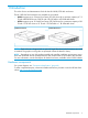
• 2. If you are replacing a disk drive, refer to “Removing a drive” (page 16) Unlatch and swing out the latch handle on the drive. Then, slide the drive into the bay (1), pressing firmly on the drive to seat it. Close the latch handle (2), pressing firmly until it locks in place. IMPORTANT: When a drive is inserted in an operational enclosure, the drive LEDs flash to indicate that the drive is seated properly and receiving power. 3. 4.
3. 4. Replace the cable(s). Confirm basic communication using LEDs See “Verifying the operating status of the disk enclosures” (page 13). Removing and replacing the I/O module 1. 2. 3. 4. Unplug the two cables from the back panel of the I/O module. See “Removing and replacing I/O Cables” (page 17) Loosen the captive retaining thumbscrew (1), and swing out the hood latch (2). 5. Slide out the I/O module (3) and set aside.
2. Press the latch (1) and slide module out (2). 3. 4. 5. Slide new power supply into the enclosure bay until it clicks into place. Replace the power cable. Confirm that the system is in normal state. See “Verifying the operating status of the disk enclosures” (page 13). Removing and replacing the fan module 1. Pinch the release buttons and slide the module out. 2.
3. 20 Confirm that the system is in normal state. See “Verifying the operating status of the disk enclosures” (page 13).
Removing and replacing the fan control card This operation is performed after HP Support determines that the enclosure is the source of the issue and requests the fan control card to be replaced WARNING! Check to make sure data on the drives is backed up Back up data if required. 1. 2. 3. 4. 5. 6. Unplug the power cables. Remove I/O cables. See “Removing and replacing I/O Cables” (page 17) Remove the fan modules. See “Removing and replacing the fan module” (page 19) Remove the rear CTO hold down bracket.
16. 17. 18. 19. Replace the fan modules. See “Removing and replacing the fan module” (page 19) Replace the I/O module cables. See “Removing and replacing the I/O module” (page 18) Replace the power cables. Apply power to the enclosure and confirm the system is powered on. See “Verifying the operating status of the disk enclosures” (page 13) 20. Confirm that the system is operating normally.
18. Replace power cables and connect the cables to a live power source. 19. Confirm system is powered on and that it is operating normally. See “Verifying the operating status of the disk enclosures” (page 13) Removing and replacing the Power Distribution Board This operation is performed after HP Support determines that the enclosure is the source of the issue and recommends that the Power Distribution Board be replaced. WARNING! Check to make sure data on the drives is backed up.
Removing and replacing the UID-health module This operation is performed after HP Support determines that the UID-health module is the source of the issue and requests the module be replaced WARNING! 1. 2. 3. Check to make sure data on the drives is backed up. Back up data if required 4. 5. 6. Unplug the power cables. Remove the I/O cables. See “Removing and replacing I/O Cables” (page 17) Remove the fan module(s) with the failed control card.
14. 15. 16. 17. 18. Tighten the retaining screws. See “Removing and replacing the enclosure” (page 22) Replace the fan modules. See “Removing and replacing the fan module” (page 19). Replace the I/O module cables. See “Removing and replacing the I/O module” (page 18) Replace power cables and connect the cables to a live power source. Confirm system is powered on and that it is operating normally.
NOTE: Depending on whether the drive cage is for LFF or SFF drives, the screws are in slightly different locations. 12. Slide the drive cage toward the front of the enclosure and lift free of the enclosure. 13. Remove the two T-15 screws attaching the back plane to the drive cage. 14. Slide the back plane toward the top of the drive cage and lift the back plane off the drive cage. 15. Place the new back plane on the drive cage and slide toward the bottom of the drive cage on to the retaining hooks. 16.
Installing the rail kit The disk enclosure can be installed into most standard server racks. To verify that your rack is supported for use with the disk enclosure, see the QuickSpecs for the disk enclosure at the HP website: http://www.hp.com. CAUTION: Install disk drives in the enclosures only after mounting the enclosures in the rack. • A disk enclosure populated with disk drives is too heavy to lift safely by a single person.
Procedures 1. Position left and right rack rails at the desired 'U' position in the rack, adjusting the rails to fit the rack, as needed. Front and Rear bottom edge of rails must align with the bottom of EIA boundary in the lowermost 'U' NOTE: Rails are marked L and R with an arrow indicating the direction in which the rail should be installed. 2. 3. Use guide pins to align the shelf mount kit to the RETMA column holes.
8. Attach rear hold down brackets by sliding the tab with the arrow pointed forward (1) into the corresponding slot on the left and right side of the rear of the chassis. Use the black headed thumb screw to secure tightly to the rail (2).
3 Troubleshooting If the enclosure does not initialize IMPORTANT: After a power failure, the system automatically returns to the On state when A/C power is restored, except in the following cases: • If both power supplies are damaged. • If there is a single power supply in the system, and it is damaged. 1. 2. 3. Ensure that power has been applied to the enclosure. Verify that the power LED is green. Verify that the power source is working: a.
Is the enclosure rear fault LED amber? Answers Possible Reasons Actions No Functioning properly. No action required Yes Rear power and UID module might not • Be sure that the rear power and UID be inserted properly, might have a module is undamaged and is fully damaged connector, or might have seated. failed. • Contact an authorized service provider for assistance. Is the System Health LED amber? Answer Possible Reasons Possible Solutions No System functioning properly. No action required.
Is the fan LED amber? 32 Answers Possible Reasons Actions No Functioning properly. No action required Yes Fan might not be inserted properly, • Be sure that the fan is undamaged might have a damaged connector, or and is fully seated. might have failed. • Contact an authorized service provider for assistance.
Recognizing disk drive failure In an HP enclosure, a steadily glowing fault LED indicates that a disk drive has failed. Other indications of failed disk drives are as follows: • ACU represents failed drives with a distinctive icon. • HP SIM can detect failed drives remotely across a network. (For more information about HP SIM, see the documentation on the Management CD.) • ADU lists all failed drives.
To minimize the likelihood of fatal system errors, take these precautions when removing failed drives: • Do not remove a degraded drive if any other drive in the array is offline (the online LED is off). In this situation, no other drive in the array can be removed without data loss. • Exceptions: • ◦ When RAID1+0 is used, drives are mirrored in pairs.
When automatic data recovery has finished, the online LED of the replacement drive stops blinking and begins to glow steadily. Failure of another drive during rebuild If a non-correctable read error occurs on another physical drive in the array during the rebuild process, the Online LED of the replacement drive stops blinking and the rebuild abnormally terminates. If this situation occurs, restart the server. The system might temporarily become operational long enough to allow recovery of unsaved data.
I/O module error codes This table describes the possible error codes appearing in the 7–segment display on the back panel of the I/O module. For information on the location of the 7–segment display, see “I/O module LEDs” (page 14) 36 Error Type Error Code Error Detail Recommended Action I/O Module Error A0 ESP generic error A1 ESP watchdog is fired A2 ESP Conflict in SAS domain (domain A/B) A3 Error in Expander communication 1. Remove the module, wait 10 seconds, reinsert the module. 2.
Error Type SAS Cable Error Disk Drive Error Error Code Error Detail Recommended Action B6 Expander firmware version mismatch with Expander firmware version in partner I/O module B8 Expander firmware image error BE Expander firmware version mismatch with ESP firmware version in own I/O module B9 SAS cable hardware error BA HP unsupported SAS cable BB Error in disk drive Check your storage administration software for more information about the problem detected and how to properly fix it.
Error Type Error Code Error Detail Recommended Action Power Supply Module Error D0 Generic error in Power Supply module 1 D1 Generic error in Power Supply module 2 If a power supply module does not have a green LED illuminated, verify that it is correctly cabled to a power source. D2 Absence of the Power Supply module 1 • Verify that the power supply is tightly inserted in the slot.
Error Type Error Code Error Detail Recommended Action E9 Failure in one or more rotors of Fan module 1 EA Failure in one or more rotors of Fan module 2 1. If a fan module has an amber LED indication, try reinserting it. 2. If none of the fans have an amber LED, replace one fan module and wait 30 seconds. 3. If the error persists, then check for new firmware releases and upgrade the enclosure firmware. New firmware versions, containing new features and defect fixes, are released periodically. 4.
4 Component identification 40 Component identification
Description CSR status 1. Chassis Bezel Ear Not a CSR part (part of drive cage) 2. Chassis Bezel Ear Not a CSR part (part of drive cage) 3. Drive Cage Not a CSR part 4. Backplane Mandatory 5. Fan module interconnect board Mandatory 6. Air guard Mandatory 7. Voltage Regulator Module (VRM) or power module Mandatory 8. Power supply Mandatory 9. Enclosure Not a CSR part 10. I/O module Mandatory 11. Fan module Mandatory 12. Rear Unit ID Mandatory 13.
5 Technical specifications Physical specifications Height/Width/Depth HP D3600 LFF: 3.44 x 17.64 x 23.54 in (8.7 x 44.8 x 59.8 cm) HP D3700 SFF: 3.44 x 17.64 x 21.48 in (8.7 x 44.8 x 54.6 cm) Weight No disk drives: 38 lb (17.2 kg) HP D3700 SFF fully populated with SFF disk drives: 54.90 lb (24.9 kg) HP D3600 fully populated with LFF disk drives: 60 lb (27.2 kg) Power and environmental specifications Temperature range (Temperature ratings shown Operating are for sea level.
Support and other resources Document conventions and symbols Convention Element Blue text: Document conventions and symbols Cross-reference links and e-mail addresses Blue, underlined text: http://www.hp.
Subscription service HP recommends that you register your product at the Subscriber's Choice for Business website: http://www.hp.com/go/e-updates After registering, you will receive e-mail notification of product enhancements, new driver versions, software updates, and other product resources. HP websites For additional information, see the following HP websites: • http://www.hp.com • http://www.hp.com/go/storage • http://www.hp.com/go/ebs • http://www.hp.com/storage/spock • http://www.hp.