HP D6000 Disk Enclosure User Guide Abstract This guide describes identification, operations, setup, configuration and utilities, troubleshooting, regulatory notices, specifications, and technical support. This guide is for an experienced service technician. HP assumes that you are qualified in the servicing of computer equipment, trained in recognizing hazards in products and are familiar with weight and stability precautions.
© Copyright 2012 Hewlett-Packard Development Company, L.P. The information contained herein is subject to change without notice. The only warranties for HP products and services are set forth in the express warranty statements accompanying such products and services. Nothing herein should be construed as constituting an additional warranty. HP shall not be liable for technical or editorial errors or omissions contained herein.
Contents Component identification ............................................................................................................... 5 Front panel components ............................................................................................................................. 5 Front panel LEDs and buttons ...................................................................................................................... 6 Rear panel components .........................................
LED behavior .......................................................................................................................................... 28 7-segment display status codes and actions....................................................................................... 29 Recognizing hard drive failure .................................................................................................................. 30 Effects of a hard drive failure ...........................................
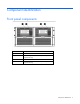
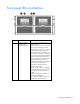
Component identification Front panel components Item Description 1 Drawer 1 2 Drawer 1 diagnostic cable access (For use by authorized HP personnel only) 3 Drawer 2 4 Drawer 2 diagnostic cable access (For use by authorized HP personnel only) Component identification 5
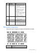
Front panel LEDs and buttons Item Description Status 1 Hard drive LEDs Normal mode (UID LED is solid) Green = The drive is online, but is not currently active. Flashing irregularly green = The drive is active and it is operating normally. Flashing green (1 Hz) = Do not remove the drive. Removing the drive may terminate the current operation and cause data loss.
Item Description Status 1 Hard drive LEDs Drive locate mode (UID LED is flashing) Green = The drive has been selected by a management application and it is operating normally. Flashing amber (1 Hz) = The drive is not selected and is indicating a predictive failure. Flashing amber/green = The drive has been selected by a management application and is indicating a predictive failure.
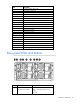
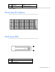
Item Description 2 Power On/UID 2 status panel 3 Fan module 1 (Drawer 2) 4 Primary I/O module (Drawer 2) 5 SAS port 1 connector 6 SAS port 2 connector 7 Power supply 3 8 UID 1 status panel 9 Fan module 1 (Drawer 1) 10 Primary I/O module (Drawer 1) 11 SAS port 1 connector 12 SAS port 2 connector 13 SAS port 1 connector 14 SAS port 2 connector 15 Secondary I/O module (Drawer 1) 16 Fan module 2 (Drawer 1) 17 Power supply 4 18 SAS port 1 connector 19 SAS port 2 connector 20
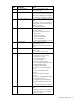
Item Description Status 2 Internal Health LED Green = System health is good. Off = System is off. 3 GSI LED* Amber = Enclosure requires service check: I/O, fan and power supply LEDs, and AC power cables to power supplies. Off = Enclosure is functioning normally. 4 UID button/LED (Drawer 2) Blue = UID LED is enabled from the UID button. Blue flashing = System is in hard drive locate mode or an enclosure firmware update is in progress. Off = UID LED is disabled.
Item Description Status Off = UID LED is disabled. * If the GSI is amber, the system needs service. Activate the associated drawer UID button to view any GSI error codes on the rear display.
Hard drive LED combinations Online/activity LED (green) Fault/UID LED (amber/blue) Interpretation On, off, or flashing Alternating amber and blue The drive has failed, or a predictive failure alert has been received for this drive; it also has been selected by a management application. On, off, or flashing Steadily blue The drive is operating normally, and it has been selected by a management application.
Operations Important Safety Information Before installing this product, read the Important Safety Information document provided. Firmware update Before configuring and using the D6000, be sure that the D6000 and all other devices in the SAS fabric are running the latest compatible versions of firmware.
3. Press and hold the Power On/Standby button. Wait and observe the system power LED and system fans. When the D6000 powers up, the system power LED illuminates solid green and the system fans spin to a high speed, and then spin down to a low speed. 4. Power up the servers. For more information, see the server documentation. Power down Be sure that the partner servers are the first units to be powered down and the last to be powered back up.
Setup Space and airflow requirements To allow for servicing and adequate airflow, observe the following space and airflow requirements when deciding where to install a rack: • Leave a minimum clearance of 63.5 cm (25.0 in) in front of the rack. • Leave a minimum clearance of 76.2 cm (30.0 in) behind the rack. • Leave a minimum clearance of 121.9 cm (48.0 in) from the back of the rack to the back of another rack or row of racks.
performs an emergency shutdown of the hard drive bays within a drawer if the temperature exceeds this limit for greater than 3 minutes. To recover the system, AC power cycle the D6000. CAUTION: To reduce the risk of damage to the equipment when installing third-party options: • Do not permit optional equipment to impede airflow around the D6000 or to increase the internal rack temperature beyond the maximum allowable limits. • Do not exceed the manufacturer’s TMRA.
Rack warnings WARNING: To reduce the risk of personal injury or damage to the equipment, be sure that: • • • • • The leveling jacks are extended to the floor. The full weight of the rack rests on the leveling jacks. The stabilizing feet are attached to the rack if it is a single-rack installation. The racks are coupled together in multiple-rack installations. Only one component is extended at a time. A rack may become unstable if more than one component is extended for any reason.
CAUTION: Always plan the rack installation so that the heaviest item is on the bottom of the rack. Install the heaviest item first, and continue to populate the rack from the bottom to the top. CAUTION: HP has not tested or validated the D6000 with any third-party racks.
WARNING: The D6000 is very heavy. To reduce the risk of personal injury or damage to the equipment: • Observe local occupational health and safety requirements and guidelines for manual material handling. • Remove all installed D6000 components from their D6000s before installing or moving the D6000s. • Use caution and get help to lift and stabilize D6000s during installation or removal, especially when the D6000 is not fastened to the rack.
• A RAID 1 mirror requires an even number of hard drives. • Drives that will be configured within an array should be the same capacity to provide the greatest storage space efficiency. NOTE: ACU does not support mixing SAS and SATA drives in the same logical volume. To install the drives: 1. Be sure all I/O bays contain either an I/O module or an I/O blank. The hard drive drawer does not open if I/O bays are empty. 2.
4. Remove the hard drive blank. 5. Prepare the hard drive.
6. Install the hard drive. WARNING: Pinch hazard—Keep hands out of front and rear of chassis when closing hard drive drawers. 7. When all drives have been installed, close the hard drive drawer. Installing optional I/O modules The D6000 ships with two I/O modules, one for each storage drawer. Installing additional I/O modules expands support from single-domain to dual-domain. CAUTION: If the I/O module is installed in an enclosure for which it was not designed, the module will not function properly.
2. To remove the I/O blank, release the I/O blank handle, pull the I/O blank handle down until it ejects the I/O blank, and then remove the I/O blank from the enclosure. 3. To install the I/O module, insert the I/O module into the enclosure and push the I/O module handle up. Be sure the I/O module is seated fully, and the I/O module handle is in the locked position. The installation installation is complete. To install the second I/O module in the other enclosure drawer, repeat the procedure.
Cabling the D6000 After installing the D6000 in a rack, connect the I/O cables and power cords to the rear panel. IMPORTANT: To achieve 6G performance, all components in a system (hard drives, disk enclosures, switches, and controllers) must be 6G capable. Mini-SAS I/O cables The D6000 does not ship with any I/O cables, but supports the use of 2.00 m (6.56 ft) mini-SAS cables. For information about the supported cables, see the QuickSpecs on the HP website (http://www.hp.com/go/d6000/quickspecs).
Configuration and utilities Configuration tools Array Configuration Utility NOTE: ACU does not support mixing SAS and SATA drives in the same logical volume.
For more information about the controller and its features, see the HP Smart Array Controllers for HP ProLiant Servers User Guide on the HP website (http://www.hp.com/support/SAC_UG_ProLiantServers_en). To configure arrays, see the Configuring Arrays on HP Smart Array Controllers Reference Guide on the HP website (http://www.hp.com/support/CASAC_RG_en). Smart Components for ROM Flash To update firmware on servers, controllers, hard drives, and direct-connect disk enclosures, use Smart Components.
• From within HP SIM ("HP Systems Insight Manager" on page 25) • From within Survey Utility • From within operating system-specific IML viewers o For NetWare: IML Viewer (does not apply to HP ProLiant DL980 Servers) o For Windows®: IML Viewer o For Linux: IML Viewer Application • From within the iLO user interface • From within HP Insight Diagnostics For more information, see the Management CD or DVD in the HP Insight Foundation suite for ProLiant.
Keeping the system current Change control and proactive notification HP offers Change Control and Proactive Notification to notify customers 30 to 60 days in advance of upcoming hardware and software changes on HP commercial products. For more information, refer to the HP website (http://www.hp.com/go/pcn). Care Pack HP Care Pack Services offer upgraded service levels to extend and expand bundled services with easy-to-buy, easy-to-use support packages that help you make the most of your server investments.
Troubleshooting When the D6000 does not power up If the D6000 does not power up: 1. Ensure that the D6000 is connected to a working AC source. 2. Ensure that the power source is working properly: 3. o Check the status using the system power LED on the rear panel. o Be sure that the Power On/Standby button was pressed firmly and held for approximately 3 seconds. Ensure that the power supplies are working properly. Check the status using the power supply LEDs. 4.
Issue Possible reasons I/O LED is amber • Possible solutions • The I/O module might not be inserted properly, it might have a • damaged connector, or it might have failed. • System power LED is off • • • • • The Power On/Standby button was not pressed firmly or held long enough. The power supply might not be inserted properly, it might have a damaged connector, or it might have failed. The system might have experienced a short. The controller firmware might be corrupted.
Status code Action 9 = Standby heartbeat failure Replace the I/O module that has an amber LED. If no I/O module has an amber LED, replace one I/O module, and then wait 30 seconds. If the GSI LED is still amber, replace the other I/O module. AC power cycle the D6000. If replacing the I/O modules does not resolve the issue, replace the drawer. 10 = Remote I/O module heartbeat failure Replace the I/O module that has an amber LED.
CAUTION: Sometimes, a drive that has previously failed may seem to be operational after the system is power-cycled or (for a hot-pluggable drive) after the drive has been removed and reinserted. However, continued use of such marginal drives may eventually result in data loss. Replace the marginal drive as soon as possible. Effects of a hard drive failure When a hard drive fails, all logical drives that are in the same array are affected.
Factors to consider before replacing hard drives You can replace hard drives without powering down the system. However, before replacing a degraded drive: • Open HP SIM and inspect the Error Counter window for each physical drive in the same array to confirm that no other drives have any errors. (For details, refer to the HP SIM documentation on the Management CD.) • Be sure that the array has a current, valid backup.
Time required for a rebuild The time required for a rebuild varies considerably, depending on several factors: • The priority that the rebuild is given over normal I/O operations (you can change the priority setting by using ACU) • The amount of I/O activity during the rebuild operation • The rotational speed of the hard drives • The availability of drive cache • The brand, model, and age of the drives • The amount of unused capacity on the drives • The number of drives in the array (for RAID
Regulatory compliance notices Regulatory compliance identification numbers For the purpose of regulatory compliance certifications and identification, this product has been assigned a unique regulatory model number. The regulatory model number can be found on the product nameplate label, along with all required approval markings and information. When requesting compliance information for this product, always refer to this regulatory model number.
• Hewlett-Packard Company P. O. Box 692000, Mail Stop 530113 Houston, Texas 77269-2000 • 1-800-HP-INVENT (1-800-474-6836). (For continuous quality improvement, calls may be recorded or monitored.) For questions regarding this FCC declaration, contact us by mail or telephone: • Hewlett-Packard Company P. O. Box 692000, Mail Stop 510101 Houston, Texas 77269-2000 • 1281-514-3333 To identify this product, refer to the part, series, or model number found on the product.
• Hewlett-Packard Company P. O. Box 692000, Mail Stop 510101 Houston, Texas 77269-2000 • 1281-514-3333 To identify this product, refer to the part, series, or model number found on the product. Modifications The FCC requires the user to be notified that any changes or modifications made to this device that are not expressly approved by Hewlett-Packard Company may void the user’s authority to operate the equipment.
For non-telecommunications products and for EU harmonized telecommunications products, such as Bluetooth® within power class below 10mW. For EU non-harmonized telecommunications products (If applicable, a 4-digit notified body number is inserted between CE and !). Please refer to the regulatory label provided on the product. The point of contact for regulatory matters is Hewlett-Packard GmbH, Dept./MS: HQ-TRE, Herrenberger Strasse 140, 71034 Boeblingen, GERMANY.
Japanese notice BSMI notice Korean notice Class A equipment Class B equipment Regulatory compliance notices 38
Chinese notice Class A equipment Vietnam compliance marking notice This marking is for applicable products only.
Electrostatic discharge Preventing electrostatic discharge To prevent damaging the system, be aware of the precautions you need to follow when setting up the system or handling parts. A discharge of static electricity from a finger or other conductor may damage system boards or other static-sensitive devices. This type of damage may reduce the life expectancy of the device. To prevent electrostatic damage: • Avoid hand contact by transporting and storing products in static-safe containers.
Specifications Environmental specifications Specification Value Temperature range* Operating 10°C to 35°C (50°F to 95°F) Maximum rate of change is 10º C/hr (50º F/hr) Storage -30°C to 60°C (-22°F to 140°F) Maximum rate of change is 20º C/hr (68º F/hr) Relative humidity** Operating 10% to 90% relative humidity (Rh), 28º C (82.4º F) maximum wet bulb temperature, non-condensing Storage 5% to 95% relative humidity (Rh), 38.7º C (101.
Support and other resources Before you contact HP Be sure to have the following information available before you call HP: • Active Health System log Download and have available an Active Health System log for 3 days before the failure was detected. For more information, see the HP iLO 4 User Guide or HP Intelligent Provisioning User Guide on the HP website (http://www.hp.com/go/ilo/docs).
providers or service partners) identifies that the repair can be accomplished by the use of a CSR part, HP will ship that part directly to you for replacement. There are two categories of CSR parts: • Mandatory—Parts for which customer self repair is mandatory. If you request HP to replace these parts, you will be charged for the travel and labor costs of this service. • Optional—Parts for which customer self repair is optional. These parts are also designed for customer self repair.
Pour plus d'informations sur le programme CSR de HP, contactez votre Mainteneur Agrée local. Pour plus d'informations sur ce programme en Amérique du Nord, consultez le site Web HP (http://www.hp.com/go/selfrepair). Riparazione da parte del cliente Per abbreviare i tempi di riparazione e garantire una maggiore flessibilità nella sostituzione di parti difettose, i prodotti HP sono realizzati con numerosi componenti che possono essere riparati direttamente dal cliente (CSR, Customer Self Repair).
HINWEIS: Einige Teile sind nicht für Customer Self Repair ausgelegt. Um den Garantieanspruch des Kunden zu erfüllen, muss das Teil von einem HP Servicepartner ersetzt werden. Im illustrierten Teilekatalog sind diese Teile mit „No“ bzw. „Nein“ gekennzeichnet. CSR-Teile werden abhängig von der Verfügbarkeit und vom Lieferziel am folgenden Geschäftstag geliefert. Für bestimmte Standorte ist eine Lieferung am selben Tag oder innerhalb von vier Stunden gegen einen Aufpreis verfügbar.
sustituciones que lleve a cabo el cliente, HP se hará cargo de todos los gastos de envío y devolución de componentes y escogerá la empresa de transporte que se utilice para dicho servicio. Para obtener más información acerca del programa de Reparaciones del propio cliente de HP, póngase en contacto con su proveedor de servicios local. Si está interesado en el programa para Norteamérica, visite la página web de HP siguiente (http://www.hp.com/go/selfrepair).
Opcional – Peças cujo reparo feito pelo cliente é opcional. Essas peças também são projetadas para o reparo feito pelo cliente. No entanto, se desejar que a HP as substitua, pode haver ou não a cobrança de taxa adicional, dependendo do tipo de serviço de garantia destinado ao produto. OBSERVAÇÃO: Algumas peças da HP não são projetadas para o reparo feito pelo cliente. A fim de cumprir a garantia do cliente, a HP exige que um técnico autorizado substitua a peça.
Support and other resources 48
Support and other resources 49
Acronyms and abbreviations ACU Array Configuration Utility ADG Advanced Data Guarding (also known as RAID 6) ADU Array Diagnostics Utility CPQONLIN NetWare Online Array Configuration Utility GSI global service indicator iLO 2 Integrated Lights-Out 2 IML Integrated Management Log ORCA Option ROM Configuration for Arrays SIM Systems Insight Manager UID unit identification Acronyms and abbreviations 50
Documentation feedback HP is committed to providing documentation that meets your needs. To help us improve the documentation, send any errors, suggestions, or comments to Documentation Feedback (mailto:docsfeedback@hp.com). Include the document title and part number, version number, or the URL when submitting your feedback.
Index 7 7-segment display 29 A ACU (Array Configuration Utility) 24 ADU (Array Diagnostic Utility) 26 airflow requirements 14 authorized reseller 42 automatic data recovery (rebuild) 32 B BSMI notice 38 buttons 5 C diagnostic tools 25 display, 7-segment 29 drive LEDs 10 E electrical grounding requirements 15 electrostatic discharge 40 environmental specifications 41 European Union notice 36 F failure, hard drive 30, 31, 33 fault tolerance, compromised 31 FCC rating label 34 features 5 Federal Communic
J Japanese notice 38 K Korean notices 38 L LED behavior 28 LED, 7-segment display 8 LED, heartbeat 6, 8 LED, system fault 6, 8 LED, system power 8 LED, UID 6 LEDs 5, 8, 10 LEDs, fan 8 LEDs, front panel 6 LEDs, hard drive 10 LEDs, I/O module 8 LEDs, power supply 8 LEDs, rear panel 8 LEDs, troubleshooting 11, 28 M maintenance guidelines 27 Management Agents 25 management tools 25 modifications, FCC notice 36 O ORCA (Option ROM Configuration for Arrays) 24 P phone numbers 42 power cord 23, 39 power requir