HP D6000 Disk Enclosure Installation Instructions Part Number: 682252-001 September 2012 Edition: 1
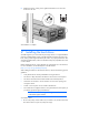
Rack warnings WARNING: To reduce the risk of personal injury or damage to the equipment, be sure that: • The leveling jacks are extended to the floor. • The full weight of the rack rests on the leveling jacks. • The stabilizing feet are attached to the rack if it is a single-rack installation. • The racks are coupled together in multiple-rack installations. • Only one component is extended at a time. A rack may become unstable if more than one component is extended for any reason.
Site requirements Select an installation site that meets the detailed installation site requirements described in the user guide on the Documentation CD. 1 Installing the enclosure WARNING: The D6000 with no drives installed weighs 72.58 kg (160.00 lb). With all drives and components installed, the enclosure can weigh up to 145.15 kg (320 lb). Before configuring your rack solution, be sure to check the manufacturer weight limits and specifications.
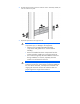
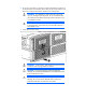
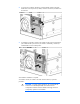
3. Slide the front end of the rail to the rack front column. When fully seated, the rack rail will lock into place. 4. Repeat the procedure for the right rack rail. WARNING: The enclosure is very heavy. To reduce the risk of personal injury or damage to the equipment: • Observe local occupational health and safety requirements and guidelines for manual material handling. • Remove all installed enclosure components from their enclosures before installing or moving the enclosures.
. Install the enclosure, making sure to tighten the thumbscrews to secure the enclosure to the rack. The installation is complete. 2 Installing the hard drives A D6000 supports up to 35 hard drives per storage drawer. For weight-distribution purposes and best-possible cooling, populate hard drive bays from the rear to the front, starting with the highest device bay ID number.
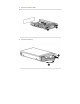
2. Be sure the I/O modules or I/O blanks are fully seated and their handles are in the locked position. The hard drive drawer does not open if I/O modules or I/O blanks are not fully seated with their handles in the locked position. WARNING: TIP HAZARD! To reduce the risk of personal injury or damage to the equipment, do not extend the hard drive drawers beyond the supporting surface when the unit is not installed in a rack.
4. Remove the hard drive blank. 5. Prepare the hard drive.
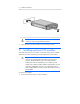
6. Install the hard drive. WARNING: Pinch hazard—Keep hands out of front and rear of chassis when closing hard drive drawers. 7. 3 When all drives have been installed, close the hard drive drawer. Installing optional I/O modules The D6000 ships with two I/O modules, one for each storage drawer. Installing additional I/O modules expands support from single-domain to dual-domain.
2. To remove the I/O blank, release the I/O blank handle, pull the I/O blank handle down until it ejects the I/O blank, and then remove the I/O blank from the enclosure. 3. To install the I/O module, insert the I/O module into the enclosure and push the I/O module handle up. Be sure the I/O module is seated fully, and the I/O module handle is in the locked position. The installation installation is complete. To install the second I/O module in the other enclosure drawer, repeat the procedure.
4 Cabling the D6000 After installing the D6000 in a rack, connect the I/O cables and power cords to the rear panel. IMPORTANT: To achieve 6G performance, all components in a system (hard drives, disk enclosures, switches, and controllers) must be 6G capable. Mini-SAS I/O cables The D6000 does not ship with any I/O cables, but supports the use of 2.00 m (6.56 ft) mini-SAS cables. For information about the supported cables, see the QuickSpecs on the HP website (http://www.hp.com/go/d6000/quickspecs).
• HP BladeSystem Deployment Guide for Solutions with 6Gb SAS BL Switches and External SAS Storage Enclosures Power cords The power cord should be approved for use in your country. The power cord must be rated for the product and for the voltage and current marked on the electrical ratings label of the product. The voltage and current rating for the cord should be greater than the voltage and current rating marked on the product. In addition, the diameter of the wire must be a minimum of 1.00 mm or 18 AWG.
WARNING: To reduce the risk of electric shock or damage to the equipment: • Do not disable the power cord grounding plug. The grounding plug is an important safety feature. • Plug the power cord into a grounded (earthed) electrical outlet that is easily accessible at all times. • Unplug the power cord from the power supply to disconnect power to the equipment. • Do not route the power cord where it can be walked on or pinched by items placed against it.