HP D6000 Disk Enclosure Maintenance and Service Guide Abstract This guide describes identification and maintenance procedures, diagnostic tools, specifications, and requirements for hardware components and software. This guide is for an experienced service technician. HP assumes you are qualified in the servicing of computer equipment, trained in recognizing hazards in products, and are familiar with weight and stability precautions.
© Copyright 2012 Hewlett-Packard Development Company, L.P. The information contained herein is subject to change without notice. The only warranties for HP products and services are set forth in the express warranty statements accompanying such products and services. Nothing herein should be construed as constituting an additional warranty. HP shall not be liable for technical or editorial errors or omissions contained herein.
Contents Customer self repair ...................................................................................................................... 5 Parts only warranty service ......................................................................................................................... 5 Illustrated parts catalog ............................................................................................................... 15 System components .................................................
Storage array specifications ..................................................................................................................... 50 Acronyms and abbreviations ........................................................................................................ 51 Documentation feedback ............................................................................................................. 52 Index ....................................................................................
Customer self repair HP products are designed with many Customer Self Repair (CSR) parts to minimize repair time and allow for greater flexibility in performing defective parts replacement. If during the diagnosis period HP (or HP service providers or service partners) identifies that the repair can be accomplished by the use of a CSR part, HP will ship that part directly to you for replacement. There are two categories of CSR parts: • Mandatory—Parts for which customer self repair is mandatory.
Obligatoire - Pièces pour lesquelles la réparation par le client est obligatoire. Si vous demandez à HP de remplacer ces pièces, les coûts de déplacement et main d'œuvre du service vous seront facturés. Facultatif - Pièces pour lesquelles la réparation par le client est facultative. Ces pièces sont également conçues pour permettre au client d'effectuer lui-même la réparation.
In base alla disponibilità e alla località geografica, le parti CSR vengono spedite con consegna entro il giorno lavorativo seguente. La consegna nel giorno stesso o entro quattro ore è offerta con un supplemento di costo solo in alcune zone. In caso di necessità si può richiedere l'assistenza telefonica di un addetto del centro di supporto tecnico HP. Nel materiale fornito con una parte di ricambio CSR, HP specifica se il cliente deve restituire dei componenti.
defekte Teil nicht zurückschicken, kann HP Ihnen das Ersatzteil in Rechnung stellen. Im Falle von Customer Self Repair kommt HP für alle Kosten für die Lieferung und Rücksendung auf und bestimmt den Kurier-/Frachtdienst. Weitere Informationen über das HP Customer Self Repair Programm erhalten Sie von Ihrem Servicepartner vor Ort. Informationen über das CSR-Programm in Nordamerika finden Sie auf der HP Website unter (http://www.hp.com/go/selfrepair).
enviara el componente defectuoso requerido, HP podrá cobrarle por el de sustitución. En el caso de todas sustituciones que lleve a cabo el cliente, HP se hará cargo de todos los gastos de envío y devolución de componentes y escogerá la empresa de transporte que se utilice para dicho servicio. Para obtener más información acerca del programa de Reparaciones del propio cliente de HP, póngase en contacto con su proveedor de servicios local.
Neem contact op met een Service Partner voor meer informatie over het Customer Self Repair programma van HP. Informatie over Service Partners vindt u op de HP website (http://www.hp.com/go/selfrepair). Garantieservice "Parts Only" Het is mogelijk dat de HP garantie alleen de garantieservice "Parts Only" omvat. Volgens de bepalingen van de Parts Only garantieservice zal HP kosteloos vervangende onderdelen ter beschikking stellen.
No caso desse serviço, a substituição de peças CSR é obrigatória. Se desejar que a HP substitua essas peças, serão cobradas as despesas de transporte e mão-de-obra do serviço.
Customer self repair 12
Customer self repair 13
Customer self repair 14
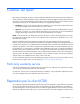
Illustrated parts catalog System components Item Description Spare part number Customer self repair (on page 5) 1 SAS I/O module 663679-001 Mandatory1 2 I/O module blank* 463756-001 Mandatory1 3 Fan 413996-001 Mandatory1 4 Power supply 579229-001 Mandatory1 5 Power block assembly 689128-001 Optional2 6 Ear bezel 663681-001 Mandatory1 7 Hard drive drawer with hard drive backplane and cables 663680-001 Optional Illustrated parts catalog 15
Item Description Spare part number Customer self repair (on page 5) 8 Rackmount kit* 432461-001 Mandatory1 9 Hard drive blank* 389015-001 Mandatory1 10 Hard drive* — — a) 300GB, 6G dual-port enterprise SAS, 15,200-rpm b) 450GB, 6G dual-port enterprise SAS, 15,200-rpm c) 600GB, 6G dual-port enterprise SAS, 15,200-rpm d) 1TB, 6G dual-port midline SAS, 7,200-rpm e) 2TB, 6G dual-port midline SAS, 7,200-rpm f) 3TB, 6G dual-port midline SAS, 7,200-rpm 517350-001 Mandatory1 517352-001 Mandatory
Mandatory: Obligatorio—componentes para los que la reparación por parte del usuario es obligatoria. Si solicita a HP que realice la sustitución de estos componentes, tendrá que hacerse cargo de los gastos de desplazamiento y de mano de obra de dicho servicio. 2 Optional: Opcional— componentes para los que la reparación por parte del usuario es opcional. Estos componentes también están diseñados para que puedan ser reparados por el usuario.
Illustrated parts catalog 18
Removal and replacement procedures Required tools The following items are required for some procedures: • T-8 Torx screwdriver • T-10 Torx screwdriver • T-15 Torx screwdriver • Phillips screwdriver Safety considerations Before performing service procedures, review all the safety information. Preventing electrostatic discharge To prevent damaging the system, be aware of the precautions you need to follow when setting up the system or handling parts.
WARNING: To reduce the risk of personal injury or equipment damage when unloading a rack: • At least two people are needed to safely unload the rack from the pallet. An empty 42U rack can weigh as much as 115 kg (253 lb), can stand more than 2.1 m (7 ft) tall, and might become unstable when being moved on its casters. • Never stand in front of the rack when it is rolling down the ramp from the pallet. Always handle the rack from both sides. WARNING: The enclosure is very heavy.
CAUTION: Always be sure that equipment is properly grounded and that you follow proper grounding procedures before beginning any installation procedure. Improper grounding can result in ESD damage to electronic components. For more information, see "Preventing electrostatic discharge (on page 19)." CAUTION: When performing non-hot-plug operations, you must power down the server blade and/or the system. Use caution when performing other operations, such as hot-plug installations or troubleshooting.
Extend the hard drive drawer 1. Be sure all I/O bays contain either an I/O module or an I/O blank. The hard drive drawer does not open if I/O bays are empty. 2. Be sure the I/O modules or I/O blanks are fully seated and their handles are in the locked position. The hard drive drawer does not open if I/O modules or I/O blanks are not fully seated with their handles in the locked position.
2. Remove the hard drive blank. To replace the blank, slide the blank into the bay until it locks into place. Hard drive CAUTION: To prevent improper cooling and thermal damage, do not operate the D6000 unless all bays are populated with either a component or a blank. Remove a drive only when there is another drive ready to install or the D6000 is powered down.
2. Remove the hard drive. To replace the component: 1. Fully extend the hard drive lever. 2. Push the hard drive all the way into the drive bay, and then close the lever. Fan IMPORTANT: Configurations using power cord part number 142263-004, located on the power cord label, require that the power cord be removed before removing a fan. Before removing a fan, do the following: • Verify the status of the fan to be replaced by reviewing rear panel LEDs and buttons (on page 46).
2. Remove the fan. CAUTION: For best cooling practices, do not operate the enclosure for extended periods with more than one component or blank removed. When removing an active component permanently, replace it with a blank. To replace the fan, install it into the fan bay and push until it locks into place. Hot-plug I/O module Before removing the component, be sure to do the following: • Verify the status of the I/O module to be replaced by reviewing rear panel LEDs and buttons (on page 46).
3. Release the I/O handle, push the I/O handle down until it ejects the I/O module, and then remove the I/O module. CAUTION: For best cooling practices, do not operate the enclosure for extended periods with more than one component or blank removed. When removing an active component permanently, replace it with a blank. To replace the component, reverse the removal procedure. Be sure the I/O module is fully seated and the I/O module handle is in the locked position.
Remove the component as indicated. To replace the component, reverse the removal procedure. Be sure the I/O module blank is fully seated and the I/O module blank handle is in the locked position. Power supply Before removing the component, be sure to do the following: • Verify the status of the power supply to be replaced by reviewing rear panel LEDs and buttons (on page 46). • Be sure that your configuration can support your actions.
2. Remove the component as indicated. To replace the component, reverse the removal procedure. Power block To remove the component: 1. Power down the D6000 ("Power down" on page 21). 2. Disconnect all cables. 3. Remove all power supplies ("Power supply" on page 27). 4. Remove all fan modules ("Fan" on page 24). 5. Remove all I/O modules ("Hot-plug I/O module" on page 25). 6. Release the hard drive drawers: a. Pull down the handle on the front of the drawer, but do not extend the drawer.
b. Push up and hold the two release mechanisms on the I/O bays, and then move the drawer forward about 15 cm (6 in).
7. Loosen the screw securing the power block to the chassis, press down on the release lever, and then slowly pull the power block out 2.54 to 5.08 cm (1 to 2 in). Do not remove the power block any further because the cable management arm is still attached. 8. Disengage the cable management arm lock from each hard drive drawer: a. Pull the mechanism up and then toward the rear of the chassis to disengage it from the locking plate. b. Slide the cable management arm off both locking plates.
9. Slowly remove the power block. The signal and power cables are still attached. 10. While supporting the power block, disconnect the signal and power cables on each side of the power block. To replace the component, reverse the removal procedure. Hard drive drawer To remove the component: 1. Power down the D6000 ("Power down" on page 21). 2. Disconnect all cables. 3. Remove all power supplies ("Power supply" on page 27). 4. Remove all fan modules ("Fan" on page 24). 5.
CAUTION: To avoid data loss, be sure that the drives are labeled and returned to the same bays they were removed from. 6. Be sure the hard drive drawer is closed completely. 7. Remove all I/O modules ("Hot-plug I/O module" on page 25). 8. Pull down the handle on the front of the drawer, but do not extend the drawer. 9. Push up and hold the two release mechanisms on the I/O bays, and then move the drawer forward about 15 cm (6 in).
11. Extend the hard drive drawer until it clicks. 12. Compress the cable management arm and push toward the drawer to lock it into place.
13. Push in to release the four locking mechanisms on the rails located on the side and bottom of the drawer. 14. Remove the hard drive drawer. To replace the component: 1. Slide the rails back into the chassis. 2. Align the top right edge of the drawer with the flange at the top of the chassis and align the four rails on the left side and bottom of the drawer bay. CAUTION: To avoid damage to the equipment, HP recommends using two people to perform this step.
3. Push the drawer in about 25 cm (10 in). 4. Release the cable management arm and expand to the rear of the chassis. 5. Push the drawer in another 25 cm (10 in). 6. Install the power block ("Power block" on page 28). WARNING: Pinch hazard—Keep hands out of front and rear of chassis when closing hard drive drawers. 7. Install the hard drives. Be sure that the drives are returned to the drive bays they were removed from. 8. Close the drawer. 9. Install all rear panel components. 10.
Troubleshooting When the D6000 does not power up If the D6000 does not power up: 1. Ensure that the D6000 is connected to a working AC source. 2. Ensure that the power source is working properly: 3. o Check the status using the system power LED on the rear panel ("Rear panel LEDs and buttons" on page 46). o Be sure that the Power On/Standby button was pressed firmly and held for approximately 3 seconds. Ensure that the power supplies are working properly.
Issue Possible reasons I/O LED is amber • Possible solutions • The I/O module might not be inserted properly, it might have a • damaged connector, or it might have failed. • System power LED is off • • • • • The Power On/Standby button was not pressed firmly or held long enough. The power supply might not be inserted properly, it might have a damaged connector, or it might have failed. The system might have experienced a short. The controller firmware might be corrupted.
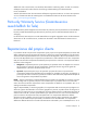
Status code Action 10 = Remote I/O module heartbeat failure Replace the I/O module that has an amber LED. If no I/O module has an amber LED, replace one I/O module, and then wait 30 seconds. If the GSI LED is still amber, replace the other I/O module. AC power cycle the D6000. If replacing the I/O modules does not resolve the issue, replace the drawer.
Effects of a hard drive failure When a hard drive fails, all logical drives that are in the same array are affected. Each logical drive in an array may be using a different fault-tolerance method, so each logical drive can be affected differently. • RAID 0 configurations cannot tolerate drive failure. If any physical drive in the array fails, all non-fault-tolerant (RAID 0) logical drives in the same array will also fail.
• Open HP SIM and inspect the Error Counter window for each physical drive in the same array to confirm that no other drives have any errors. (For details, refer to the HP SIM documentation on the Management CD.) • Be sure that the array has a current, valid backup. • Use replacement drives that have a capacity at least as great as that of the smallest drive in the array. The controller immediately fails drives that have insufficient capacity.
• The rotational speed of the hard drives • The availability of drive cache • The brand, model, and age of the drives • The amount of unused capacity on the drives • The number of drives in the array (for RAID 5 and RAID 6 with ADG) Allow approximately 1 minute per gigabyte for the rebuild process to be completed. System performance is affected during the rebuild, and the system is unprotected against further drive failure until the rebuild has finished.
Component identification Front panel components Item Description 1 Drawer 1 2 Drawer 1 diagnostic cable access (For use by authorized HP personnel only) 3 Drawer 2 4 Drawer 2 diagnostic cable access (For use by authorized HP personnel only) Diagnostic cable access IMPORTANT: Use of the diagnostic cable connectors is reserved for authorized HP personnel only.
To access the connectors for diagnostic cables, use a small flat-head screwdriver to lift up and release the access tab.
Front panel LEDs and buttons Item Description Status 1 Hard drive LEDs Normal mode (UID LED is solid) Green = The drive is online, but is not currently active. Flashing irregularly green = The drive is active and it is operating normally. Flashing green (1 Hz) = Do not remove the drive. Removing the drive may terminate the current operation and cause data loss.
Item Description Status 1 Hard drive LEDs Drive locate mode (UID LED is flashing) Green = The drive has been selected by a management application and it is operating normally. Flashing amber (1 Hz) = The drive is not selected and is indicating a predictive failure. Flashing amber/green = The drive has been selected by a management application and is indicating a predictive failure.
Item Description 2 Power On/UID 2 status panel 3 Fan module 1 (Drawer 2) 4 Primary I/O module (Drawer 2) 5 SAS port 1 connector 6 SAS port 2 connector 7 Power supply 3 8 UID 1 status panel 9 Fan module 1 (Drawer 1) 10 Primary I/O module (Drawer 1) 11 SAS port 1 connector 12 SAS port 2 connector 13 SAS port 1 connector 14 SAS port 2 connector 15 Secondary I/O module (Drawer 1) 16 Fan module 2 (Drawer 1) 17 Power supply 4 18 SAS port 1 connector 19 SAS port 2 connector 20
Item Description Status 2 Internal Health LED Green = System health is good. Off = System is off. 3 GSI LED* Amber = Enclosure requires service check: I/O, fan and power supply LEDs, and AC power cables to power supplies. Off = Enclosure is functioning normally. 4 UID button/LED (Drawer 2) Blue = UID LED is enabled from the UID button. Blue flashing = System is in hard drive locate mode or an enclosure firmware update is in progress. Off = UID LED is disabled.
Item Description Status Off = UID LED is disabled. * If the GSI is amber, the system needs service. Activate the associated drawer UID button to view any GSI error codes on the rear display.
Hard drive LED combinations Online/activity LED (green) Fault/UID LED (amber/blue) Interpretation On, off, or flashing Alternating amber and blue The drive has failed, or a predictive failure alert has been received for this drive; it also has been selected by a management application. On, off, or flashing Steadily blue The drive is operating normally, and it has been selected by a management application.
Specifications Environmental specifications Specification Value Temperature range* Operating 10°C to 35°C (50°F to 95°F) Maximum rate of change is 10º C/hr (50º F/hr) Storage -30°C to 60°C (-22°F to 140°F) Maximum rate of change is 20º C/hr (68º F/hr) Relative humidity** Operating 10% to 90% relative humidity (Rh), 28º C (82.4º F) maximum wet bulb temperature, non-condensing Storage 5% to 95% relative humidity (Rh), 38.7º C (101.
Acronyms and abbreviations ACU Array Configuration Utility ADG Advanced Data Guarding (also known as RAID 6) ADU Array Diagnostics Utility CPLD complex programmable logic device GSI global service indicator IML Integrated Management Log PIC peripheral interface controller SAS serial attached SCSI SATA serial ATA SES SCSI Enclosure Services SIM Systems Insight Manager UID unit identification Acronyms and abbreviations 51
Documentation feedback HP is committed to providing documentation that meets your needs. To help us improve the documentation, send any errors, suggestions, or comments to Documentation Feedback (mailto:docsfeedback@hp.com). Include the document title and part number, version number, or the URL when submitting your feedback.
Index 7 hard drive LEDs 48, 49 hard drive, failure of 38 7-segment display 37 I A I/O module 25 I/O module blank 26 automatic data recovery (rebuild) 40 B buttons 42 C cautions 19 components 15, 19, 42 compromised fault tolerance 39 connectors 42, 45 customer self repair (CSR) 5 D device numbers 48 diagnosing problems 36 diagnostic cable access 42 display, 7-segment 37 drive LEDs 48 E electrostatic discharge 19 environmental specifications 50 F failure, hard drive 38, 39, 41 fans, removing 24 fau
S safety considerations 19 SAS hard drive LEDs 48 specifications 50 static electricity 19 system components 15, 42 T troubleshooting 36, 49 W warnings 19 Index 54