HP DC04 SAN Director Switch Hardware Reference Guide Abstract This document provides information about setting up, configuring, and maintaining the HP DC04 SAN Director Switch (DC04 SAN Director). It is intended for system administrators and technicians with knowledge of SANs and DC SAN Directors.
© Copyright 2008, 2013 Hewlett-Packard Development Company, L.P. © Copyright 2008, 2013 Brocade Communications Systems, Incorporated The information contained herein is subject to change without notice. The only warranties for HP products and services are set forth in the express warranty statements accompanying such products and services. Nothing herein should be construed as constituting an additional warranty. HP shall not be liable for technical or editorial errors or omissions contained herein.
Contents 1 DC04 SAN Director overview......................................................................6 Features..................................................................................................................................6 Hardware components..............................................................................................................7 Port side of the DC04 SAN Director.......................................................................................
Monitoring blower assembly status............................................................................................62 Monitoring WWN bezel (logo plate) and WWN card status.......................................................63 5 Replacing DC04 SAN Director FRUs...........................................................65 Replacing the chassis door......................................................................................................65 Removing the chassis door....................
Documentation feedback....................................................................................................97 Related information.................................................................................................................97 HP websites......................................................................................................................97 Rack stability..........................................................................................................
1 DC04 SAN Director overview The DC04 SAN Director (part numbers AR478A, AR478B, AR479A, AR479B) represents the next generation of advanced Fibre Channel (FC) enterprise-class platforms used to intelligently interconnect storage devices, hosts, and servers in a SAN. The DC04 SAN Director satisfies the most demanding RAS, performance, and scalability requirements, while delivering investment protection, interoperability, and fabric-based intelligence advantages.
• • Universal ports self-configure as E_Ports, F_Ports, FL_Ports, Ex_Ports, and M_Ports. ◦ 10-Gb/s (FC10-6) are E_Ports only. ◦ Ex_Ports are supported on the FR4-18i router blade, FX8-24 and FX8-24E extension blades, and on the FC8-xx blades with Integrated Routing license installed. ◦ 10-Gb/s CEE ports are supported on the FCOE10-24 blade. Ships FICON and FICON Cascading ready. FICON CUP is available, but requires an optional license.
only with Fabric OS 7.1.0a and later), increased to up to four per chassis with Fabric OS 6.4.x. ◦ • FCOE10-24: 24-port (24 10-GbE ports) CEE-based FCoE blade, enabling enhanced connectivity over existing Ethernet infrastructure. Up to two blades per chassis. Modular hot-swappable FS8-18 encryption blade: 16-port, up to 4 blades per chassis, supporting data cryptographic (encryption/decryption) and data-compression capabilities.
Figure 1 Port side of the DC04 SAN Director (sample configuration) 1. FC8-48 port blade 3. Control processor blade (CP8) 2. Core switch blade (CR4S-8) 4.
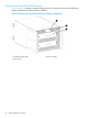
Non-port side of the DC04 SAN Director Figure 3 (page 10) displays a sample configuration of the non-port side view of the DC04 SAN Director without the port side exhaust kit installed. Figure 3 Non-port side of the DC04 SAN Director (sample configuration) 1. WWN bezel (logo plate) 2. Power supply 10 DC04 SAN Director overview 3.
DC04 SAN Director blades Table 1 (page 11) describes the Director, CP, and core switch blades that are available for the DC04 SAN Director. Table 1 Blades available for the DC04 SAN Director Description DC04 SAN Director CP blade Name Function CP8 The CP8 blade manages all other blades in the DC04 SAN Director. There are two CP8 blades for redundancy. This CP blade is compatible with the SN8000B 8-Slot SAN Backbone Director, SN8000B 4-Slot SAN Director, DC SAN Backbone Director, and DC04 SAN Director.
Table 1 Blades available for the DC04 SAN Director (continued) Description Name Function HP DC SAN Director Multiprotocol Extension blade FX8-24 The FX8-24 blade enables FCIP functionality over an existing IP infrastructure. It has 12 FC ports, 10 1-GbE ports, and 2 10-GbE ports. This Director blade is compatible with the DC04 SAN Director, DC SAN Backbone Director, SN8000B 4-Slot SAN Director, and SN8000B 8-Slot SAN Backbone Director. The blade supports IPsec encryption on one 10-GbE port.
• Dual CP Blades that enable hot, nondisruptive, fast firmware upgrades • Each CP Blade contains one serial port and two Ethernet ports, for management and for service. • Standby CP Blade to monitor diagnostics to ensure it is operational, in case a failover is required.
Security Table 2 (page 14) highlights some of the key security features available for the DC04 SAN Director running Fabric OS 6.2.0a or later, and for other HP enterprise-class platforms running Fabric OS 5.2.0 or later. For details, contact HP.
• HP B-series Advanced Performance Monitor Director Switch LTU All • HP B-series Extended Fabric Director Switch LTU All • HP DC SAN Director Inter-Chassis Link Cable Kit Four 2-meter copper cables used to connect two DC SAN Directors via an ICL License. NOTE: Required for HP DC SAN Director 8 Inter-Chassis Link LTU.
NOTE: Optional Advanced Extension license is available on the DC SAN Director and DC04 SAN Director for the MP Extension blade (AP865A) on an individual SAN Director slot basis. • HP MP Blade Performance Extension LTU Activates the high performance extension services for either IP or FC connectivity in the B-series MP Router Blade (FR4-18i). IP and FC extension services are mutually exclusive. This option also includes the Encryption Services license.
Optional hardware kits Table 3 (page 17) lists the DC04 SAN Director optional hardware kits.
Table 3 DC04 SAN Director orderable hardware (continued) Accessory Part number1 HP 2 m Multi-mode OM2 LC/SC FC Cable 221691-B21 HP 5 m Multi-mode OM2 LC/SC FC Cable 221691-B22 HP 15 m Multi-mode OM2 LC/SC FC Cable 221691-B23 HP 30 m Multi-mode OM2 LC/SC FC Cable 221691-B26 HP 50 m Multi-mode OM2 LC/SC FC Cable 221691-B27 Optical cables (mSFP-LC type cables) HP B-series 1.5 m MM OM3 mSFP/LC FC Cable BK784A HP B-series 2.
2 DC04 SAN Director Installation This chapter provides information and instructions for installing a DC04 SAN Director. You can set up and install the DC04 SAN Director in the following ways: • As a standalone unit on a flat surface. • In a 19-in EIA cabinet using the port side exhaust kit (provided).
1. 2. 3. Provide a space that is 9 rack units (9U) high, 61.19 cm (24.09 in) deep, and 43.74 cm (17.22 in) wide. 1U is equal to 4.45 cm (1.75 in). The DC04 SAN Director can be installed facing in either direction, provided that serviceability and cooling requirements are met. Plan for cable management before installing the chassis.
Table 5 DC04 SAN Director shipping carton contents (continued) • Blade slot filler panels (for slots not filled by blades) • Port-side exhaust kit • Shipping bracket kit • WWN cards • WWN bezel (logo plate) • Power supplies • Blower assemblies • Vertical cable management fingers • Chassis door The accessory kit includes: • HP product documentation • ESD grounding strap • RS-232 serial cable, with an adapter at one end to provide an RJ-45–style connector • HP B-series 2G USB Drive IMPORTANT: Order SFP trans
Table 6 Rack mount kit contents (continued) Item Description Quantity D 10-32 x 1.27 cm (0.5 in) Phillips screw (blue Loctite on threads) 12 E 10-32 x 1.60 cm (0.63 in) Phillips screw with square cone washer 12 F 10-32 clip nut for cabinets that have rails with round holes 8 G 10-32 retainer nut for cabinets that have rails with square holes 8 H Alignment washer for cabinets that have rails with square holes 12 I 6-32 x 0.635 cm (0.
Table 7 Torque requirements Screw size Torque 6-32 x .635 cm (0.25 in) Phillips screw 10 cm-kg (8.75 in-lb) 10-32 x 1.60 cm (0.63 in) Phillips screw 36.86 cm-kg (32 in-lb) Installing the cabinet hardware 1. 2. Position the DC04 SAN Director in the equipment cabinet so that the non-port side has access to cool intake air. Install the mounting nuts in the cabinet rail locations shown in Figure 5 (page 23).
3. Install the shelf. a. You can adjust the shelf to a length of 68.58 to 78.74 cm (27 to 31 in) to accommodate the cabinet size. To lengthen or shorten the shelf, loosen the four 6-32 screws in the four slots on the shelf (I-4 through I-7 in Figure 4 (page 22)) and adjust the shelf to the desired length. Once adjusted, tighten the four 6-32 screws. b. Secure the shelf to the cabinet with eight 10-32 screws with washers (E in Figure 4 (page 22)), two screws in each corner of the shelf.
5. Secure the top-rail assembly (A in Figure 4 (page 22)) to the air-duct assembly. (See Figure 8 (page 25)). a. You can adjust the top-rail assembly to a length of 68.58 to 78.74 cm (27 to 31 in) to accommodate the cabinet size. To lengthen or shorten the top-rail assembly, loosen the two 6-32 screws (I-3 in Figure 4 (page 22)) and adjust the top-rail assembly to the desired length. The length will be approximately the length of the adjustable shelf. Once adjusted, tighten the two 6-32 screws. b.
NOTE: The screws, clip nuts, and retainer nuts used to secure the DC04 SAN Director to the cabinet are provided in the DC04 SAN Director hardware accessory kit. To install the DC04 SAN Director in the cabinet: 1. Remove the chassis door from the DC04 SAN Director. See Removing the chassis door (page 65). 2. Use a lift to raise the chassis to the correct level. Position the lift as close as possible to the rack. 3. If applicable, lock the wheels on the lift. 4.
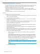
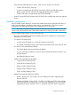
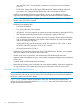
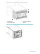
1. 2. Before installing the DC04 SAN Director in the cabinet, remove the 10 flathead 6-32 screws located on both the left and right side chassis panels. See Figure 11 (page 28). Install both side plates using the ten 6-32 panhead screws supplied with the kit. NOTE: The left and right side plates are different. The left side and right side plates are marked “A” and “B” respectively. See Figure 11 (page 28). NOTE: The side plates have five sets of discrete holes, marked 27 through 31.
Figure 11 Installing the shipping brackets on the DC04 SAN Director Figure 12 Installing the DC04 SAN Director with shipping brackets 28 DC04 SAN Director Installation
Powering on the DC04 SAN Director CAUTION: Use the power cords supplied. Ensure that the facility power receptacle is the correct type, supplies the required voltage, and is properly grounded. To power on the DC04 SAN Director: 1. Connect the AC power cords to the power supply assemblies. One to four power cords are required, depending on electrical service. 2.
right in the lower group of 12 ports. They are labeled FC on the front panel diagram. The two 10-GbE ports are 0 and 1 and are in the left-hand column above the FC ports. They are labeled 10GE on the front panel diagram. The 1-GbE ports are 0 through 9 and are in both columns above the FC and 10GE ports. They are labeled GE on the front panel diagram.
• Route the cables to both the left and right sides of the switch through the cable management fingers. • Route port cables and other cables away from the LEDs to ensure that the LEDs are visible. Figure 14 Vertical cable management finger assemblies Installing transceivers and attaching cables Follow these steps to install SFPs, SFP+s, mSFPs (FC8-64 port card only), or XFPs (FC10-6 port card only) and cables to the DC04 SAN Director. NOTE: Use mSFP optical transceivers only with the FC8-64 port blade.
NOTE: For Fabric OS 6.4.0 and later, three DCX chassis can be supported in a triangular ICL configuration, as long as the third chassis is housed in an immediate adjacent rack so that the cables reach the ICL ports. The ICL cables and the ICL connectors (see Figure 15 (page 33)) are color-coded and labeled for ease of installation. Connect the ICL cables using one of the configurations shown in Figure 16 (page 34) through Figure 19 (page 37).
Figure 15 ICL connectors on CR4S-8 blade 1. Status LED 4. ATTN LED 2. Power LED 5. ICL connector 3.
Figure 16 DC04 SAN Director ICL cabling 34 1. Chassis 1 5. ICL connector (ICL 1) 2. Core switch blades (CR4S-8) 6. ICL connector (ICL 0) 3. Control processor blades (CP8) 7. ICL cables 4. Port blades 8.
Figure 17 DC04 SAN Director to DC SAN Director ICL cabling (configuration 1) 1. Chassis 1 (DC04) 5. ICL connector (ICL 1) 2. Core switch blades (CR4S-8) 6. ICL connector (ICL 0) 3. Control processor blades (CP8) 7. ICL cables 4. Port blades 8. Chassis 2 (DC SAN Backbone) NOTE: For clarity, the two sets of cables are drawn differently in Figure 18 (page 36) and Figure 19 (page 37).
Figure 18 DC04 SAN Director to DC SAN Director 3-way ICL cabling (configuration 2) 36 1. Chassis 1 (DC04) 4. Chassis 3 (DC SAN Backbone) 2. Core switch blades 5. ICL connector (ICL 1) 3. Chassis 2 (DC SAN Backbone) 6.
Figure 19 DC04 SAN Director to DC SAN Director 3-way ICL cabling (configuration 3) 1. Chassis 1 4. Chassis 3 2. Core Switch blades 5. ICL connector (ICL 1) 3. Chassis 2 6. ICL connector (ICL 0) The same general configuration applies regardless of which chassis are used. To keep all three chassis in the same rack, use any combination of DC SAN Directors and DC04 SAN Directors, with the exception of three DC SAN Director chassis.
3 DC04 SAN Director login and configuration This chapter provides information and instructions for configuring the DC04 SAN Director. Configuration overview NOTE: If an FS8-18 encryption blade is installed, see the Fabric OS Encryption Administrator's Guide for information on configuring the encryption functions. You must configure the DC04 SAN Director before it is connected to the fabric. All configuration commands must be entered through the active CP blade.
tip /dev/ttyb -9600 When the terminal emulator application stops reporting information, press Enter. The following login prompt appears: CP0 Console Login: 6. Log in to the DC04 SAN Director as admin. The default password is password. At the initial login, the user is prompted to enter new admin and user passwords. Fabric OS (swDir) swDir login: admin Password: Please change your passwords now. Use Control-C to exit or press 'Enter' key to proceed. Password was not changed.
4. Set up the CP1 IP address by entering the ipaddrset -cp 1 command: swDir:admin> ipAddrSet -cp 1 Enter the configuration information at the prompts. This is a sample IP configuration: swDir:admin> ipaddrset -chassis Ethernet IP Address [0.0.0.0]: 123.123.123.120 Ethernet Subnetmask [0.0.0.0]: 123.123.123.123 Fibre Channel IP Address [0.0.0.0]: Fibre Channel Subnetmask [0.0.0.0]: Issuing gratuitous ARP...Done. Committing configuration...Done.
Customizing a switch name The switch name of the DC04 SAN Director can be up to 15 characters long; can include alphabetic, numeric, and underscore characters; and must begin with an alphabetic character. NOTE: Changing the name causes a domain address format RSCN to be issued To customize the switch name: 1. Enter switchName followed by the new name in double quotation marks. swDir:admin> switchName "swBrocadeDCX5" Committing configuration... Done. swBrocadeDCX5:admin> 2.
To set the domain ID: 1. Enter the switchDisable command to disable the DC04 SAN Director. 2. Enter the configure command. 3. Enter y at the Fabric parameters prompt: Fabric parameters (yes, y, no, n): [no] y 4. Enter a unique domain ID: Domain: (1.239) [1] 3 5. 6. Complete the remaining prompts or press Ctrl+D to accept the settings and exit. Enter the switchEnable command to re-enable the DC04 SAN Director. Setting the date and time The date and time settings are used for logging events.
Setting the time zone To set the time zone: 1. If necessary, log on to the DC04 SAN Director by Telnet using the admin account. 2. Enter the tsTimeZone command as follows: switch:admin> tstimezone [--interactive]/ [, timezone_fmt] The following example shows how to change the time zone to US/Mountain.
2. Position one of the optical transceivers so that the key is oriented correctly to the port. Insert the transceiver into the port until it is firmly seated and the latching mechanism clicks. Transceivers are keyed so that they can only be inserted with the correct orientation. If the transceiver does not slide in easily, ensure that it is correctly oriented. 3. Position a cable so that the key (the ridge on one side of the cable connector) is aligned with the slot in the transceiver.
An easy way to back up configuration information is to enable logging on your Telnet session, and then run the following commands and save the output in a file on a secure host. • configShow • ipaddrShow • licenseShow • switchShow Keep copies of key data such as passwords, license keys, and IP addresses in a secure location. NOTE: Passwords are not saved in the configuration file, and are not uploaded during a configUpload.
4 Monitoring DC04 SAN Director system components The DC04 SAN Director is engineered for reliability and requires no routine operational steps or maintenance. This chapter provides information about determining the status of each component using LEDs and CLI commands. Monitoring Director blade status To determine the status of a Director blade: 1. Observe the LEDs on the blade. 2. 3. • Figure 20 (page 47) shows the FC8-16. • Figure 21 (page 48) shows the FC8-32.
Figure 20 FC8-16 Director blade 1. Power LED 3. FC port 2. Status LED 4.
Figure 21 FC8-32 Director blade 48 1. Power LED 3. FC port 2. Status LED 4.
Figure 22 FC8-48 Director blade 1. Power LED 3. FC port 2. Status LED 4.
Figure 23 FC8–64 Port blade 50 1. Status LED 3. FC port 2. Port LED 4.
Figure 24 FC10-6 Director blade 1. Power LED 3. FC port 2. Status LED 4.
Figure 25 FR4-18i router blade 52 1. Power LED 3. FC port 2. Status LED 4.
Figure 26 FS8-18 encryption blade 1. Power LED 3. FC port 2. Status LED 4.
Figure 27 FX8-24 and FX8-24E Extension blades 1. 10-GbE ports 0–1 5. FC ports 0–5 2. 1-GbE ports 0–3 6. Power LED 3. 1-GbE ports 4–9 7. Status LED 4.
Figure 28 FCOE10-24 FCoE blade 1. 10-GbE FCoE ports 12–23 3. Power LED 2. 10-GbE FCoE ports 0–11 4. Status LED Table 9 Director and application blade LED descriptions LED purpose Power LED Status LED Color Status Recommended action Steady green Blade has been enabled. No action required No light (LED is off) Blade has not been enabled. Ensure blade is firmly seated. No light (LED is off) Blade is either healthy or does not have power. Verify that the power LED is on.
Table 9 Director and application blade LED descriptions (continued) LED purpose Color Steady amber Status Blade is faulty. Recommended action Ensure blade is firmly seated and verity status using the slotShow command. If the LED remains amber, contact HP. Slow-flashing amber (on Blade is not seated correctly or is Pull blade out and reseat it. If LED 2 seconds, then off 2 faulty. continues to flash, replace blade.
Table 9 Director and application blade LED descriptions (continued) LED purpose 10-GbE Port Status (FCOE10-24) 1 Color Status Recommended action Flickering green Port is online, with traffic flowing No action required through it. Fast-flashing amber (on 1/4 second, then off 1/4 second) Transceiver or port is faulty. Change the transceiver or reset the switch from the workstation. No light (LED is off) Port is offline. Verify that the power LED is on; verify the transceiver and cable.
Monitoring control processor blade (CP8) status To determine the status of a CP8 blade: 1. Observe the LED indicators on the CP blade (see Figure 29 (page 58)). The LED patterns may temporarily change during POST and other diagnostic tests. For information about how to interpret the LED patterns, see Table 10 (page 59). 2. Verify the port blade status by entering the slotShow and haShow commands. Figure 29 Control processor blade (CP8) 58 1. Status LED 5. Console port (10101) 2. Power LED 6.
Table 10 (page 59) describes the CP blade LED patterns and the recommended actions for those patterns. Table 10 CP8 blade LED descriptions LED purpose Color Status Recommended action Power Steady green CP blade has valid power. No action required No light (LED is off) CP blade does not have incoming Ensure blade is firmly seated and power. has power. No light (LED is off) CP blade is either healthy or does Verify that the power LED is on. not have power.
Monitoring core switch blade (CR4S-8) status To determine the status of a core switch blade: 1. Observe the LED indicators on the core switch blade (see Figure 30 (page 60)). The LED patterns may temporarily change during POST and other diagnostic tests; for information about how to interpret the LED patterns, see Table 11 (page 61). 2. Verify the core switch blade status by entering the slotShow and haShow commands. Figure 30 Core switch blade (CR4S-8) 1. Status LED 4. ATTN LED 2. Power LED 5.
Table 11 (page 61) describes the core switch blade LED patterns and the recommended actions for those patterns. Table 11 CR4S-8 blade LED descriptions LED purpose Color Status Recommended action Power Steady green CP blade has valid power. No action required No light (LED is off) CP blade does not have incoming power. Ensure blade is firmly seated and has power. No light (LED is off) CP blade is either healthy or does not have power. Verify that the power LED is on.
Figure 31 Power supply 1. Power LED Table 12 (page 62) describes the power supply LED patterns and the recommended actions for those patterns. Table 12 Power supply LED descriptions LED purpose Color Status Recommended action Power No light (LED is off) Power supply does not have incoming power and is not providing power to the DC04 SAN Director. Ensure power supply is firmly seated, DC04 SAN Director has incoming power, both power cables are connected, and AC power switches are on.
Table 13 Blower assembly LED descriptions LED purpose Color Status Recommended action Power No light (LED is off) Blower assembly does not have incoming power. Ensure that the blower assembly is firmly seated and has power. Steady green Blower assembly has incoming power. No action required No light (LED is off) Blower assembly is either healthy Ensure that the blower assembly or does not have incoming has incoming power. power. Steady amber Blower assembly has a failure (full or partial).
Figure 33 WWN bezel (logo plate) 64 Monitoring DC04 SAN Director system components
5 Replacing DC04 SAN Director FRUs This chapter provides information for replacing field-replaceable components. IMPORTANT: The FRUs in the DC04 SAN Director can be removed and replaced without special tools. The DC04 SAN Director can continue operating during many of the FRU replacements if the conditions specified in the procedure are followed. Replacing the chassis door The chassis door must be installed to ensure that the DC04 SAN Director meets EMI and other regulatory certifications.
orientation of the blades in the DC04 SAN Director, the finger assemblies are attached to the uprights of the mounting rack. The replacement procedure for the vertical cable management fingers takes less than five minutes. You will need a #1 Phillips screwdriver. Removing a cable management finger assembly CAUTION: Wear a grounded ESD strap when handling DC04 SAN Director components. The DC04 SAN Director chassis provides a grounding connection above the power connectors.
• SFP or extended form-factor pluggable XFP (FC10-6 Director blade only) transceivers (as needed) • Optical cables (as needed) CAUTION: A filler panel should be removed only when being replaced with a Director blade, or a filler panel. Any slot that is not occupied by a Director blade should be occupied by a filler panel to ensure correct cooling of the chassis and protection from dust. Removing a blade CAUTION: Wear a grounded ESD strap when handling a DC04 SAN Director blade.
12. If the blade is not being replaced by another blade, install a filler panel. Figure 36 DC04 SAN Director blade (FC8-48 shown) Installing a blade Slots are numbered from 1 through 8, from bottom to top when facing the port side of the DC04 SAN Director. Port and application blades can be installed in slots 1-2 and 7-8. CAUTION: Wear a grounded ESD strap when handling a blade. Use the grounding connections above the power connectors on the chassis. 1. 2.
Removing a filler panel CAUTION: A filler panel should be removed only when being replaced with a port or application blade, or another filler panel. Any slot that is not occupied by a blade must be occupied by a filler panel to ensure correct cooling of the chassis and protection from dust. To remove a filler panel: 1. Remove the chassis door. See Removing the chassis door (page 65). 2. Use the Phillips screwdriver to unscrew the thumb screw at the bottom of the panel. 3.
Determining whether or not to replace a CP blade The following events might indicate that a CP blade is faulty: • The status LED on the CP blade is amber, or the power LED is not lit. • The CP blade does not respond to Telnet commands, or the serial console is not available. • The slotShow command does not show that the CP blade is enabled. • The haShow command indicates an error. • The clock is inaccurate, or the CP blade does not boot up or shut down properly.
Recording critical DC04 SAN Director information Back up the DC04 SAN Director configuration before you replace a CP blade. See the Fabric OS Administrator's Guides for backup information. To record critical DC04 SAN Director information: 1. Log in to the functioning CP blade as admin, using either a Telnet or a serial console connection. 2.
d. Enter the haShow command from the functioning CP blade (the new active CP blade) to verify the failover.
To remove a CP blade: 1. Remove the chassis door. See Removing the chassis door (page 65). 2. Log in to the active CP as admin. You can use a serial cable or Telnet, Web Tools, or Fabric Manger. Determine which CP is active using the haShow command or view the active LED on the front of the CP. 3. If the faulty CP is the active CP, issue the haFailover command. Wait until the failover has completed. Use the haShow command to verify that the CPs are synchronized and the failover is complete. 4.
3. Verify that HA is enabled using the haShow command. The command output includes HA Enabled Heartbeat Up and HA-state in sync. If HA is not enabled, POST is not complete, or the CP blades have not achieved redundancy, wait one or two minutes and re-enter the command until you can verify that redundancy has been achieved. 4. Enter the slotShow command.
◦ EM messages that indicate a problem with a core switch blade ◦ Function fail messages for the core switch blade master For more information about error messages, see the Fabric OS Message Reference. Removing a core switch blade The DC04 SAN Director continues to operate while a core switch blade is being replaced. CAUTION: Wear a grounded ESD strap when handling a CR4S-8 blade. Use the grounding connections above the power connectors on the chassis.
7. 8. Pack the faulty core switch blade in the packaging provided with the new core switch blade, and contact the DC04 SAN Director supplier for the procedure for returning the faulty blade. Replace the chassis door. See Installing the chassis door (page 65). Replacing a power supply The DC04 SAN Director can continue operating during the replacement if at least one power supply continues operating. The replacement procedure for each power supply takes less than five minutes.
Figure 41 Power supply Replacing a blower assembly IMPORTANT: The DC04 SAN Director can continue operating during the replacement if the second blower assembly is operating. The procedure for removing each blower assembly takes less than 5 minutes.
Figure 42 Blower assembly Replacing the WWN bezel (logo plate) and WWN card The WWN cards contain fully redundant circuits and typically do not require replacement. Two WWN cards are located beneath the WWN bezel (logo plate). Allow approximately 20 minutes to replace a WWN card.
To determine the status of a WWN card: 1. Observe the LED indicators on the WWN bezel and verify that they reflect the actual status of the components. The WWN bezel covers the WWN cards and allows its LEDs to shine through. The LEDs on the WWN bezel provide a consolidated view of the port, CP, and CR blade status (see Table 15 (page 80)). If a blade slot has a filler panel installed, the corresponding LEDs on the WWN card do not light up.
Removing the WWN bezel (logo plate) and WWN card To remove the WWN bezel and WWN card: CAUTION: Wear a grounded ESD strap when handling the WWN card. Use the grounding connections above the power connectors on the chassis. 1. 2. 3. 4. 5. Open a Telnet session to the DC04 SAN Director and log in to the active CP as admin. The default password is password. Verify that you are logged into the active CP. Run the haShow command to determine the active CP. Remove the two screws from the WWN bezel.
Figure 43 WWN bezel (logo plate) and WWN card Installing the WWN bezel (logo plate) and WWN card CAUTION: Wear a grounded ESD strap when handling the WWN card. Use the grounding connections above the power connectors on the chassis. To install the WWN bezel and WWN card: 1. Unpack the new WWN card and save the packaging for the faulty WWN card. 2. Hold the card by the pull tab and insert the WWN cable onto the WWN module until it is fully seated.
Replacing SFPs, SFP+s, mSFPs, and XFPs NOTE: The 8-Gb/s mSFPs and SFP+s autonegotiate at 2, 4, and 8 Gb/s. The 4-Gb/s SFPs autonegotiate at 1, 2, and 4 Gb/s. The XFP transceivers are used only with the FC10-6 port card. They should not be used in any 1 GE port. To remove an SFP, SFP+, or XFP (FC10-6 blade only) transceiver, pull the bail down and out, sliding the transceiver out of the port or application blade.
Figure 45 mSFP optical transceiver 1. Pull tab 2. mSFP optical transceiver Replacing an mSFP optical transceiver 1. 2. Insert the cable into the new transceiver until the latching mechanism clicks. Position the optical transceiver so that the key is oriented correctly to the port. Insert the transceiver into the port until it is firmly seated and the latching mechanism clicks. Transceivers are keyed so that they can be inserted only with the correct orientation.
• A surface to place the old chassis on, such as a second lift or the pallet originally provided with the old chassis • #2 Phillips screwdriver Verifying the need for replacing the chassis To verify that it is necessary to replace the chassis, ensure that the components are firmly seated, troubleshoot the chassis following the list in this section, and then contact your support provider with any remaining questions about whether the chassis should be replaced.
Table 18 Critical information checklist Configuration information Location of config-switch.txt file: Location of config-miscinfo.txt file: IP address, subnet mask: WWN for DC04 SAN Director: SAN profile Location of SANbefor.txt file: Notes regarding nsshow output: Notes regarding nsallshow output: Notes regarding switchshow output: Notes regarding fabricshow output: Output from supportshow command Location of spptshow.
3. Record the DC04 SAN Director values on a workstation. a. Record the WWN value: Enter the wwn command, and then copy the command output into a file named config-miscinfo.txt. rsl8-st03-dcx-1:admin> wwn 10:00:00:60:69:00:00:0a b. Record the IP address information. Enter the ipAddrShow -sw command, and then copy the command output into the config-miscinfo.txt file. rsl8-st03-dcx-1:admin> ipAddrShow -sw SWITCH Ethernet IP Address: 10.32.50.12 Ethernet Subnetmask: 255.55.0.0 Fibre Channel IP Address: 1.2.
Factory Serial Num: Manufacture: Update: Time Alive: Time Awake: FT02X805BE2 Day: 26 Month: Day: 14 Month: 207 days 3 days 3 3 Year: 2007 Year: 2009
Disconnecting from the network and the fabric To disconnect from the network and fabric: 1. Shut down the DC04 SAN Director using the sysShutdown command. rsl8-st03-dcx-1:admin> sysshutdown This command will shutdown the operating systems on your switch. You are required to power-cycle the switch in order to restore operation. Are you sure you want to shutdown the switch [y/n]?y HA is disabled Stopping blade 1 Shutting down the blade.... Stopping blade 4 Shutting down the blade....
Installing the replacement chassis CAUTION: A fully-populated DC04 SAN Director (four FC8-64 port cards, 256 ports) weighs approximately 68 kg (150 lb) and requires a hydraulic or assisted lift to install it. If the DC04 SAN Director is installed in a cabinet, ensure that the cabinet is balanced and secured mechanically and that the removal and installation procedure does not compromise cabinet stability. 1. 2. 3. 4. 5.
Configuring the new chassis serial number To configure a new chassis serial number: 1. Open a CLI session (Telnet or serial) to the DC04 SAN Director and log in as root. The root and factory account disclaimer is displayed. • Log in using Telnet. Use the IP address of the DC04 SAN Director through Telnet and log in as root.
1. Log in to the DC04 SAN Director as admin. rsl8-st03-dcx-1:admin> login login: admin password: xxxxxxxx rsl8-st03-dcx-1:admin> 2. Enter the slotShow command and verify that all the installed cards are detected and that their status is operational (enabled).
4. Verify that all the IP address information is correct by entering the ipaddrshow command and comparing the results with the IP information recorded in the config-miscinfo.txt file. rsl8-st03-dcx-1:admin> ipaddrshow SWITCH Ethernet IP Address: 10.32.50.12 Ethernet Subnetmask: 255.55.0.0 Fibre Channel IP Address: 1.2.3.4 Fibre Channel Subnetmask: 255.255.255.0 CP0 Ethernet IP Address: 10.32.50.10 Ethernet Subnetmask: 255.55.0.0 HostName : cp0 Gateway Address: 10.32.40.1 CP1 Ethernet IP Address: 10.32.50.
Verifying that the configuration of the fabric is correct HP recommends that you copy the command outputs from this section into a file. To verify correct configuration of the fabric: 1. Create an “after” SAN profile by entering the following commands and copying the output to a text file named SANafter.
3. Resolve any issues or unintentional changes to the DC04 SAN Director or fabric. • If there are any mechanical problems, try reseating the associated component. • If the configuration information is not correct for the DC04 SAN Director, modify as required. If necessary, the configuration saved before the replacement can be downloaded using the configDownload command.
Table 19 Cable routing table for DC04 SAN Director (48 ports shown) (continued) Slot/port Slot Cable labels Port 18 19 20 21 22 23 24 25 26 27 28 29 30 31 32 33 34 35 36 37 38 39 40 41 42 43 44 45 46 47 48 96 Replacing DC04 SAN Director FRUs Switch end Connected device Device end Slot/port of device
6 Support and other resources HP technical support For worldwide technical support information, see the HP support website: http://www.hp.
• http://www.hp.com/support/manuals • http://www.hp.com/support/downloads Rack stability Rack stability protects personnel and equipment. WARNING! 98 To reduce the risk of personal injury or damage to equipment: • Extend leveling jacks to the floor. • Ensure that the full weight of the rack rests on the leveling jacks. • Install stabilizing feet on the rack. • In multiple-rack installations, fasten racks together securely. • Extend only one rack component at a time.
Typographic conventions Table 20 Document conventions Convention Element Blue text: Table 20 (page 99) Cross-reference links and email addresses Blue, underlined text: http://www.hp.
A Technical specifications This appendix provides information for the DC04 SAN Director. General specifications The DC04 SAN Director is compliant with United States and International safety and EMC Electromagnetic Compatibility standards. Table 21 (page 100) lists the general specifications for the DC04 SAN Director.
System architecture Table 22 DC04 SAN Director system architecture FC Ports Up to 256 ports, universal (E_Port, F_Port, FL_Port, Ex_Port, and M_Port) Control processor Redundant (active/standby) control processor modules Scalability Full fabric architecture: 239 switches maximum Performance 1.063 Gb/s line speed, full duplex 2.125 Gb/s line speed, full duplex 4.25 Gb/s line speed, full duplex 8.50 Gb/s line speed, full duplex 10.
Table 22 DC04 SAN Director system architecture (continued) Media types Hot-pluggable, industry-standard SFP or XFP (FC10-6 only), LC connector: • SWL, up to 500 m (1,640 ft) • LWL, up to 10 km (6.2 mi) • ELWL, up to 80 km (49.
Table 24 System FRU weights (continued) FRU Weight FX8-24 Multi Protocol Extension blade 4.2 kg (9.2 lb) without media FX8-24E Enhanced Multi Protocol Extension blade 4.2 kg (9.2 lb) without media FCOE10-24 FCoE blade 3.72 kg (8.2 lb) without media Port card filler panel 1.5 kg (3.2 lb) Power supply 2.45 kg (5.4 lb) Blower assembly 5.73 kg (12.6 lb) WWN bezel 0.3 kg (0.6 lb) Vertical cable management fingers 0.45 kg (1.0 lb) WWN bezel 0.3 kg (0.6 lb) Chassis door 2.09 kg (4.
Table 25 DC04 SAN Director power specifications Specification Value Input voltage Range: 85–264 VAC Auto-volt, Nominal: 100 to 240 VAC Input frequency range 47–63 Hz; Nominal: 50–60 Hz Power supply output (each) Low line (85–132 VAC), 1,000 W; High line (180–264 VAC), 2,000 W AC inrush current 20 A maximum, peak System power consumption AC power consumption is configuration-specific.
Table 27 Power cord types (international) (continued) Plug style NEMA 5–20P 125V only USA, Canada, Mexico, other locations NEMA L6-20 USA, Canada, Mexico, other locations CEE-7/7 “Schuko” Continental Europe BS-1363A AS 3112 IEC-60309 Australia/New 32A-6h, Zealand 230V C20 20A-250V 12 AWG connect to in-cabinet power strip only. All locations Country only.
Table 27 Power cord types (international) (continued) Plug style NEMA 5–20P 125V only USA, Canada, Mexico, other locations NEMA L6-20 USA, Canada, Mexico, other locations CEE-7/7 “Schuko” Continental Europe BS-1363A AS 3112 IEC-60309 Australia/New 32A-6h, Zealand 230V C20 20A-250V 12 AWG connect to in-cabinet power strip only.
Table 27 Power cord types (international) (continued) Plug style NEMA 5–20P 125V only USA, Canada, Mexico, other locations NEMA L6-20 USA, Canada, Mexico, other locations CEE-7/7 “Schuko” Continental Europe BS-1363A AS 3112 IEC-60309 Australia/New 32A-6h, Zealand 230V C20 20A-250V 12 AWG connect to in-cabinet power strip only.
Table 28 DC04 SAN Director environmental requirements Acceptable range during non-operation nl Condition Acceptable range during operation Ambient temperature 10° to 40°C outside switch (50° to 104°F) -40° to +70°C outside switch (-40° to 158°F) Humidity 5% to 85% RH noncondensing, at 40°C, 10% to 93% RH noncondensing, at 70°C with maximum gradient of 10% per hour Altitude Up to 3 km (10,000 ft) above sea level 0 to 12 km (40,000 ft) above sea level Shock 20G, 6 ms duration, half-sine wave 33G,
Table 29 Supported single mode cable speeds and distances Cable type 9 microns 1 Speed Minimum distance Maximum distance (LWL) Maximum distance (ELWL) 2 Gb/s 2m 10,000 m 25,000 m1 4 Gb/s 2m 10,000 m 25,000 m1 8 Gb/s 2m 10, 000 m 25,000 m1 The maximum distance for the AN211A is 30,000 m. Table 30 Supported multi-mode cable speeds and distances Cable type Speed Minimum distance Maximum distance (SWL) 50 microns 2 Gb/s 0.5 m 300 m (OM2); 500 m (OM3) 4 Gb/s 0.
B Intelligent blades This appendix provides information for the following blades: • B-series MP Router blade (FR4-18i) • HP DC Switch Encryption FC blade (FS8-18) • HP Multiprotocol Extension blade (FX8-24) • HP StoreFabric Enhanced Multiprotocol Extension Blade (FX8-24E) • DC SAN Director 10/24 FCoE blade (FCOE10-24) B-series MP Router blade (FR4-18i) overview NOTE: The B-series MP Router blade (FR4-18i) is used in the DC04 SAN Director.
1. 2. 3. 4. Select an empty slot in the Director. Ensure the latches on the FR4-18i blade are unscrewed and open. Slide the FR4-18i blade into the open slot. Close the latches, tighten the screws, and power on the blade using the ON/OFF slider switch (see Figure 46 (page 111)). The FR4-18i blade begins POST. After POST is complete, the firmware version on the blade will autolevel with the firmware version on the active CP. 5.
Configuring FCIP and FC Routing Services and enabling the ports The ports on the FR4-18i blade are initially set to persistently disabled. If you want to enable the FC ports as a standard E_Port or F_Port, use the portcfgpersistentenable command to enable the ports. If you are using the FC ports as EX_Ports, you must configure the FC Routing Services feature prior to enabling the ports. The GbE ports can be used only after you have configured FCIP and enabled the VE_Ports.
Recommendations for cable management Manage cables as follows: • Plan cable management before installing the blade. • Leave at least one meter of slack for each port cable. This provides room to remove and replace the blades, and helps prevent the cables from being bent to less than the minimum bend radius. HP DC Switch Encryption FC blade (FS8-18) overview NOTE: The HP DC Switch Encryption FC blade (FS8-18) is used in the DC SAN Director.
Configuring the FS8-18 blade For information on configuring the encryption functions, see the Fabric OS Encryption Administrator's Guide. Cabling the FS8-18 blade To cable the FS8-18 blade: 1. Install the SFP transceivers in the FC and GbE ports, as required: a. Remove the rubber plugs from the ports to be used. b. Position the transceiver so that it is oriented correctly and insert it into a port until it is firmly seated and the latching mechanism clicks.
NOTE: The port diagram on the front panel uses the abbreviations GE for 1-GbE ports and 10GE for 10-GbE ports. If the FX8-24 blade is operating in 10-GbE mode, the other end of the circuit must be an FX8-24 blade operating in either 10-GbE mode or dual mode with the corresponding VE_Ports in 10-GbE mode. IMPORTANT: The 10-GbE SFPs used in the FX8-24 blade are not interchangeable with the 10 Gb/s FC SFPs used in the FC16-32/48 blades.
• ◦ FC Routing Services are used over the FCIP link. ◦ Fabrics connected through FCIP merge if the ports are configured as VE_Ports; they do not merge if they are configured as VEX_Ports. If VE_Ports are used in an FC Routing Services backbone fabric configuration, then the backbone fabric merges, but the EX_Port-attached edge fabrics do not merge. For more information, see the Fabric OS Administrator’s Guide 7.0.1.
• Multiple circuits per trunk ◦ Four per trunk through the GbE ports ◦ Ten per trunk through the 10-GbE ports • SOTCP with reorder resistance • FastWrite over FCIP • Virtual E_Ports • FCIP QoS • Support for 200-ms RTT (on a limited number of GbE ports) • Adaptive Rate Limiting (licensable) • FICON Accelerator (licensable) • TCP performance graphing in Web Tools • FCIP Tunnels • ◦ A maximum of 10 FCIP tunnels is allowed for all GbE ports.
• JTAG support • Blade power and status LEDs • Link status LEDs for each port The FCOE10-24 blade also provides the following features: 118 • FCoE switching • CEE switching • L2 Ethernet protocols STP/MSTP/RSTP, 802.1q, and Link Aggregation (802.
C Regulatory information This section contains regulatory notices. For important safety, environmental, and regulatory information, see Safety and Compliance Information for Server, Storage, Power, Networking, and Rack Products, available at http:// www.hp.com/support/Safety-Compliance-EnterpriseProducts.
D Environmental regulation compliance This section describes the China RoHS environmental regulatory compliance requirements for the Director. China RoHS The following are the requirements of the People's Republic of China- Management Methods for Controlling Pollution by Electronic Information products.
Table 31 Hazardous substances (continued) Name of the Component Hazardous/Toxic Substance/Elements Lead (PB) Mercury (Hg) Cadmium (Cd) Hexavalent Chromium (CR6+) Polybrominated Biphenyl (PBB) Polybrominated Diphenyl Ether (PBDE) SFPs (optical cable connectors) X O O O O O Sheet metal X O O O O O Chassis assembly X O O O O O Mechanical brackets and slides X O O O O O Slot filler X O O O O O Cable management comb X O O O O O Cable comb O O O O O O Cables
Environmental regulation compliance
E Port numbering templates Print or copy the templates on the following pages and use them to document the port numbering pattern for the DC04 SAN Director.
DC04 SAN Director templates The following port templates are provided for the DC04 SAN Director: • Port side populated with four FC8-64 port blades, two CR4S-8 blades, and two CP8 blades • Port side populated with four FC8-48 port blades, two CR4S-8 blades, and two CP8 blades • Port side populated with four FC8-32 port blades, two CR4S-8 blades, and two CP8 blades • Port side populated with four FC8-16 port blades, two CR4S-8 blades, and two CP8 blades • FC10-6 port blades • FR4-18i router blades
Figure 49 Port side populated with four FC8-16 port blades, two CR4S-8 blades, and two CP8 blades Figure 50 FC10-6 port blades DC04 SAN Director templates 125
Figure 51 FR4-18i router blades 126 Port numbering templates
Figure 52 FS8-18 encryption blades DC04 SAN Director templates 127
Figure 53 FX8-24/FX8-24E Extension blade 128 Port numbering templates
Figure 54 FCOE10-24 FCoE blade DC04 SAN Director templates 129
Glossary This glossary defines acronyms and terms used in this guide and is not a comprehensive glossary of computer terms. A ACL Access control list. A data protection feature used to restrict access to data resources based on defined policies. AES Advanced Encryption Standard. An encryption security technology. API Application Programming Interface. ASIC Application-Specific Integrated Circuit. B B-series FC switches and FICON directors manufactured for HP by Brocade Communications Systems, Inc.
F fabric A network of one or more FC switches that transmit data between any two N_Ports on any of the switches. failover An automatic method for transferring operations from a failed system to a secondary, identical system. FC Fibre Channel. A comprehensive set of standards for concurrent communication among servers, storage systems, and peripheral devices. FC-SP Fibre Channel Security Protocol. A security protocol that protects in-transit data. FCC Federal Communications Commission.
LTU License to use. LUN Logical unit number. An identification scheme for storage disks. LWL Long-wave laser. M MIB Management Information Base (B-series). MP Router Multiprotocol Router. MPIO Multipath I/O (Microsoft software). MUAs Multiple user accounts. N NTP Network time protocol. NVRAM Nonvolatile RAM P PID Port identifier. platform A combination of supported hardware components and operating system on a server from a specific vendor. POST Power-on self-test.
SP Service pack. A collection of software updates. SPOCK Single Point of Connectivity Knowledge. An HP website as the primary portal to obtain detailed information about supported HP product configurations (http://www.hp.com/storage/spock). An HP Passport account is required for access. SR Short Reach SSH Secure Shell. A security encryption protocol. SWL Short-wave laser. T topology The physical structure of interconnected components that form a network. U V VF Virtual fabric.
Index B back up configuration, DC04, 44 bezel, WWN, DC04 replacing, 79 blade FCOE10-24, 117 FR4-18i, 110 FX8-24, 114 blade, DC04 CP, LEDs, 59 CP, status, 58 CR, LEDs, 61 CR4S-8, status, 60 Director, replacing, 66 port, status, 46 blades weight, 102 blades, DC04 available for, 11 support for, 6 blower assembly, DC04 replacing, 78 status, 62 C cable management fingers, DC04, replacing, 65 cables, managing, DC04, 30 chassis door, DC04, replacing, 65 China RoHS, 120 compliance, environmental regulation, 120 co
replacing, 65 chassis door replacing, 65 CP blade LEDs, 59 replacing, 69 CR blade LEDs, 61 CR4S-8 blade replacing, 75 Director blade replacing, 66 filler panel replacing, 68 power supply, 61 LEDs, 62 replacing, 77 removing and replacing, 65 WWN bezel replacing, 79 WWN card replacing, 79 FX8-24 blade, 114 H hardware components, DC04, 7 hardware kits, DC04, 17 help obtaining, 97 HP technical support, 97 I ICL kit, DC04, 31 installation tasks, DC04, 19 Inter-Chassis Link cable kit, DC04, 31 IP address, confi
HP Subscriber's Choice for Business, 97 product manuals, 97 weight, DC04 SAN Director, 102 WWN bezel, DC04, 79 replacing, 79 WWN card, DC04, 79 replacing, 79 status, 63 136 Index