HP SN8000B 4-Slot SAN Backbone Director Switch Hardware Reference Guide Abstract This document provides information about setting up, configuring, and maintaining the HP SN8000B 4-Slot SAN Director Switch (SN8000B 4-Slot SAN Director). It is intended for system administrators and technicians with knowledge of SANs and Directors.
© Copyright 2011, 2013 Hewlett-Packard Development Company, L.P. © Copyright 2011, 2013 Brocade Communications Systems, Incorporated The information contained herein is subject to change without notice. The only warranties for HP products and services are set forth in the express warranty statements accompanying such products and services. Nothing herein should be construed as constituting an additional warranty. HP shall not be liable for technical or editorial errors or omissions contained herein.
Contents 1 SN8000B 4-Slot SAN Director overview........................................................7 Features..................................................................................................................................7 Hardware components .............................................................................................................8 Port side of the Director.........................................................................................................
Monitoring Monitoring Monitoring Monitoring Monitoring Monitoring the Director blade status..........................................................................................49 CP blade status......................................................................................................54 the core switch blade status.....................................................................................56 the power supply status....................................................................
Recording critical Director and SAN information....................................................................89 Disconnecting from the network and fabric............................................................................93 Removing components from the chassis.................................................................................93 Installing a replacement chassis...........................................................................................
E Port numbering templates.........................................................................122 SN8000B 4-Slot SAN Director templates.................................................................................130 F Director power supply requirements...........................................................136 Glossary..................................................................................................137 Index........................................................................
1 SN8000B 4-Slot SAN Director overview The SN8000B 4-Slot SAN Director models (part numbers QK711A, QK711B, QK712A, and QK712B) represent the next generation of advanced FC enterprise-class platforms used to intelligently interconnect storage devices, hosts, and servers in a SAN. The SN8000B 4-Slot SAN Director satisfies the most demanding RAS, performance, and scalability requirements, while delivering investment protection, interoperability, and fabric-based intelligence advantages.
Hardware components The Director features a modular and scalable mechanical construction that allows a wide range of flexibility in installation, fabric design, and maintenance. The chassis can be mounted with the cables facing the front of the equipment rack or to the rear. NOTE: HP highly recommends that you mount the chassis with the air intake (nonport side) mounted towards the cool air aisle, not towards the aisle where heated exhaust air comes from other components.
• Modular hot-swappable FRUs: ◦ Two blower assemblies. ◦ Two power supplies (100–240 VAC autosensing). – At 110 VAC (nominal), a minimum of two power supplies is required, regardless of the number of port or application blades. This configuration does not support high availability. – HP recommends 220 VAC (nominal). A second power supply is required to support high availability. – Redundant AC primary power connections ensure high availability.
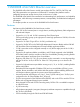
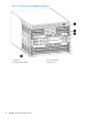
Figure 1 Port side of the 4-Slot SN8000B SAN Director 10 1. Port blade 2. Core switch blade 3. Control processor blade 4.
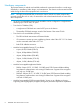
Figure 2 Port side with exhaust kit installed Nonport side of the Director Figure 3 (page 12) shows a configuration of the nonport side view of the Director without a port side exhaust kit installed.
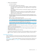
Figure 3 Nonport side of the SN8000B 4-slot SAN Director (sample configuration) 12 1. WWN bezel (logo plate) 2. Power supply 3. Blower assembly 4.
Director blades Table 1 (page 13) describes the Director, CP blades, and core switch blades that are available for the SN8000B 4-Slot SAN Director. Table 1 Blades available for the Director Description Name Function SN8000B 4-Slot SAN Director CP Blade CP8 The CP8 blade provides for management of all other blades in the Director. There are two CP8 blades for redundancy.
Table 1 Blades available for the Director (continued) Description Name Function 4-Slot SAN Director, SN8000B 8-Slot SAN Director, DC SAN Director, and DC04 SAN Director. The blade supports IPsec encryption over both 10GbE ports. This blade requires Fabric OS 7.1.0a or later.
• NVRAM containing the serial number, revision information, and part number • Background health-check daemon • Memory scrubber, self-test, and bus ping to determine if a bus is functioning • RASlog messages • SMI-S compliance • Status LEDs • Predictive diagnostics analysis through Fabric Watch • SNMP (including version 3) integration with higher-layer managers • Vertical cable management fingers Software features Fabric OS allows any FC-compliant device to attach to the switches as long as
Table 2 Security features (continued) IP filters (block listeners) Configurable RSCN suppression by port Secure passwords (centralized control via RADIUS/CHAP) NTPv3 (to synchronize timestamps) MUAs (up to 255) Event auditing RBAC Change tracking Administrative domains/Virtual fabrics Firmware change alerts in HP B-series SAN Network Advisor Boot PROM password reset Persistent port disable Password hardening policies Persistent domain ID Upfront login in Web Tools E_Port disable Network mana
NOTE: For the latest information on supported software components, see the product QuickSpecs available from the HP website: http://www.hp.com/go/sn8000b/quickspecs. Optional hardware kits Table 3 (page 17) lists the optional hardware kits for the Director.
Table 3 SN8000B 4-Slot SAN Director optional hardware (continued) Accessory Part number1 HP 30 m Premier Flex OM4 FC cable QK736A HP 50 m Premier Flex OM4 FC cable QK737A HP 10 m Premier Flex MPO/MPO Multi-mode OM4 8 fiber cable QK729A HP 50 m Premier Flex MPO/MPO Multi-mode OM4 8 fiber cable QK731A HP PremierFlex OM3+ Optical Cables HP .
2 SN8000B 4-Slot SAN Director installation This chapter provides information for installing a Director. You can set up and install the Director: • As a standalone unit on a flat surface • In a 19-inch EIA cabinet, using the Rack Mount Kit and port side exhaust kit (provided). Time and items required for installation Table 4 (page 19) describes the main installation and setup tasks and the estimated installation time, based on a fully populated SN8000B 4-Slot SAN Director (four FC port blades).
Site preparation and unpacking the Director IMPORTANT: For important safety, environmental, and regulatory information, see Safety and Compliance Information for Server, Storage, Power, Networking, and Rack Products, available at http://www.hp.com/support/Safety-Compliance-EnterpriseProducts. To ensure correct installation and operation, you must: 1. Provide a space that is 9U high, 61.29 cm (24.09 inch) deep, and 43.74 cm (17.22 inch) wide. 1U is equal to 4.45 cm (1.75 inch). 2.
9. Verify the contents of the carton against the packing list. 10. Use a pallet jack or other assisted lift to transport the chassis on the shipping tray to the installation area. The plastic shipping tray cannot fit through doorways that are less than 91 cm (36 inch) wide. 11. Remove the port side exhaust kit, shipping bracket kit, accessory kit, packing foam, and antistatic plastic from the chassis and set aside. 12. Remove the chassis door from the Director 13. Remove the cable management fingers. 14.
Installing the Director in a rack Air flows into the director through its nonport side and out through the exhaust vent on the side of the unit. The port side exhaust kit is designed to route the airflow out the exhaust vents on the port side of the unit while mounted in the equipment cabinet. This section provides instructions for installing a SN8000B 4-Slot SAN Director in a 48.26-cm (19-inch) EIA cabinet using the port-side exhaust kit for cabinets with rail-to-rail depth of 68.58 to 78.
Figure 4 Rack Mount Kit hardware Torque requirements Use the torque settings listed in Table 7 (page 23) when tightening screws that secure the Rack Mount Kit and SN8000B 4-Slot SAN Director to the equipment cabinet. Table 7 Torque requirements Screw size Torque 6-32 x .635 cm (0.25 inch) Phillips screw 10 cm-kg (8.75 in-lb) 10-32 x 1.60 cm (0.63 inch) Phillips screw 36.86 cm-kg (32 in-lb) Installing the cabinet hardware 1. 2.
The location shown in Figure 5 (page 24) is an example. The shelf and Director can be installed anywhere in the cabinet that has 9U of space available. Figure 5 Clip and retainer nut locations on cabinet rails 3. Install the shelf. a. You can adjust the shelf to a length of 68.58 to 78.74 cm (27 to 31 inch) to accommodate the cabinet size.
4. Install the air-duct assembly by inserting it down into the side slot on the shelf. Ensure that the tabs of the assembly align and engage with the slots in the shelf. See Figure 7 (page 25).
5. Secure the top-rail assembly (A in Figure 4 (page 23)) to the air-duct assembly. See Figure 8 (page 26). a. You can adjust the top-rail assembly to a length of 68.58 to 78.74 cm (27 to 31 inch) to accommodate the cabinet size. To lengthen or shorten the top-rail assembly, loosen the two 6-32 screws (I-3 in Figure 4 (page 23)) and adjust the top-rail assembly to the desired length. The length will be approximately the length of the adjustable shelf.
NOTE: The screws, clip nuts, and retainer nuts used to secure the Director to the cabinet are provided in the SN8000B 4-Slot SAN Director hardware accessory kit. To install the SN8000B 4-Slot SAN Director in the cabinet: 1. Remove the chassis door from the Director. See “Removing the chassis door” (page 62). 2. Use a lift to raise the chassis to the correct level. Position the lift as close as possible to the rack. 3. If applicable, lock the wheels on the lift. 4.
2. Install both side plates using the ten 6-32 panhead screws supplied with the kit. NOTE: The left and right side plates are different. The left side and right side plates are marked “A” and “B” respectively. See Figure 11 (page 29). NOTE: The side plates have five sets of discrete holes, marked 27 through 31. Use the holes that correspond to the cabinet rail-to-rail depth. See Table 8 (page 28). Tighten the screws to 10 in/lb. 3. 4. Install the Director in the cabinet.
Figure 11 Installing the shipping brackets on the Director Figure 12 Installing the Director with shipping brackets Installing the Director in a rack 29
Powering on the Director CAUTION: Use the supplied power cords. Ensure that the facility power receptacle is the correct type, supplies the required voltage, and is properly grounded. To power on the Director: 1. Connect two AC power cords to the power supply assemblies. 2. Connect the power cords to a power source with a voltage of 200 to 240 VAC, 47 to 63 Hz or to a power source with voltage of 110 to 120 VAC, 47 to 63 Hz.
• FS8-18 encryption blade—FC ports are numbered 0 through 15 from bottom to top. The two 10/100/1000 Base-T ports are numbered from the bottom as GE0 and GE1. • FX8-24 port blade—Ports are numbered in groups. FC ports are numbered 0 through 11 in two vertical rows of six ports, starting from the bottom left and bottom right in the lower group of 12 ports. They are labeled FC on the front panel diagram. The two 10-GbE ports are 0 and 1 and are in the left column above the FC ports.
for port, application, or encryption blades. Unused slots must contain filler panels to maintain adequate cooling. Managing cables You can organize and manage cables in a variety of ways, including using the cable channels on the port sides of the cabinet or patch panels. HP recommends that you use the pair of vertical cable management finger assemblies to keep the cables from hanging down in front of other blades and to keep the LEDs visible.
Installing transceivers and attaching cables NOTE: mSFP optical transceivers are compatible with the FC8-64 port blade only. Although they fit in other blades, the configuration is unsupported and generates an error. To install SFP+ or mSFP (FC8-64 port card only) transceivers and cables to the Director: CAUTION: The minimum radius to which a 50 micron cable can be bent under full tensile load is 5.1 cm (2 inch). For a cable under no tensile load, that minimum is 3.0 cm (1.2 inch). 1.
Figure 14 QSFP cable connections 1. Chassis 1 34 SN8000B 4-Slot SAN Director installation 2.
3 Director login and configuration This chapter provides information about configuring the SN8000B 4-Slot SAN Director. NOTE: If an FS8-18 encryption blade is installed, see the Fabric OS Encryption Administrator's Guide for information on configuring the encryption functions. You can find the document on the Manuals page of the HP Business Support Center website: http://h18006.www1.hp.com/storage/networking/b_switches/index.html Select B-series Director Switches.
Stop bits—1 Flow control—None For most UNIX systems, enter the following string at the prompt: tip /dev/ttyb -9600 However, if ttyb is in use, enter: tip /dev/ttya -9600 When the terminal emulator application stops reporting information, press Enter. The following login prompt appears: CP0 Console Login: 6. Log in to the Director as admin. The default password is passw0rd (the sixth character is a zero). At the initial login, you are prompted to enter new admin and user passwords.
3. Set up the CP0 IP address by entering the ipAddrSet -cp 0 command: swDir:admin> ipAddrSet -cp 0 Enter the configuration information at the prompts. 4. Set up the CP1 IP address by entering the ipAddrSet -cp 1 command: swDir:admin> ipAddrSet -cp 1 Enter the configuration information at the prompts. The following is a sample IP configuration: swDir:admin> ipAddrSet -chassis swDir:admin> ipaddrset -chassis Ethernet IP Address [0.0.0.0]: 192.168.1.1 Ethernet Subnetmask [0.0.0.0]: 255.255.255.
Customizing a switch name The Director switch name can be up to 30 characters; can include alphabetic, numeric, and underscore characters; and must begin with an alphabetic character. NOTE: Changing the switch name causes a domain address format RSCN to be issued. To customize the switch name: 1. Enter the switchName command followed by the new name in double quotation marks. swDir:admin> switchName "swModularSwitch5" Committing configuration... Done. swModularSwitch5:admin> 2.
2. Use the date command to set the date and time. The syntax is date "mmddHHMMyy" Where: • mm is the month. Valid values are 01 through 12. • dd is the date. Valid values are 01 through 31. • HH is the hour. Valid values are 00 through 23. • MM is minute. Valid values are 00 through 59. • yy is the year. Valid values are 00 through 99. NOTE: Values greater than 69 are interpreted as 1970 through 1999. Values less than 70 are interpreted as 2000-2069.
2. Enter the tsClockServer command. The syntax is switch:admin> tsClockServer "ntp1;ntp2" where ntp1 is the IP address or DNS name of the first NTP server that the switch must access, and ntp2 is the optional second NTP server. The operand “ntp1;ntp2” is optional. By default, this value is LOCL, which uses the local clock of the principal or primary switch as the clock server. The tsClockServer command accepts multiple server addresses in IPv4, IPv6, or DNS name formats.
3. Position a cable so that the key (the ridge on one side of the cable connector) is aligned with the slot in the transceiver. Insert the cable into the transceiver until the latching mechanism clicks. Cables are keyed so that they can be inserted with the correct orientation only. If a cable does not slide in easily, verify the orientation. 4. 5. 6. 7. Repeat Step 1 through Step 3 for the remaining ports. Organize the cables. See “Managing cables” (page 32).
5. Verify the Director and port status using the switchShow -qsfp command. The following example shows an SN8000B 4-Slot Director with a core blade installed in slot 3. Your output will look similar. NOTE: The state of an unconnected QSFP (shown QSFP 0 and Ports 0-3 in the example) appears as No_SigDet . This is different from the state of an unconnected SPF, which appears as No_Synch. QSFP 7 (ports 3/28–3/31, Index 748–751) shows a connected QSFP.
Installing SFP+ and mSFP transceivers and cables Complete the following steps to install SFP-type optical transceivers. NOTE: mSFP transceivers are compatible only with the FC8-64 port blade. While they will fit in other blades, such a configuration is unsupported and will generate an error. 1. Add the optical transceivers and cables to the Fibre Channel ports. The ports are color-coded to indicate which can be used in the same port group for trunking (trunking port groups can be up to eight ports).
2. 3. 4. Use Telnet to log on to the switch as admin. From the workstation, enter the switchShow command to verify the status of switches and ports. From the workstation, enter the fabricShow command to verify the status of the fabric. To back up the configuration: 1. Enter configUpload -vf to upload virtual fabric data. 2. Enter configUpload to upload the Director configuration to the server so that it is available for downloading to a replacement Director.
4 Monitoring system components The Director is engineered for reliability and requires no routine operational steps or maintenance. This chapter describes the CLI commands and LED patterns that you use to determine the status of each component. For more information, see the Web Tools Administrator’s Guide and the Fabric OS Administrator’s Guide 7.0.1. Commands To monitor the health of the Director, use the switchShow and chassisShow commands.
14 1 14 820e00 id N8 Online FC F-Port 10:00:00:05:1e:f9:72:47 15 1 15 820f00 id N8 Online FC F-Port 10:00:00:05:33:26:0e:8a 16 1 16 821000 id N8 Online FC F-Port 10:00:00:05:33:26:0e:8b 17 1 17 821100 id N8 Online FC F-Port 10:00:00:05:33:48:6b:eb 18 1 18 821200 id N8 Online FC F-Port 10:00:00:05:1e:f9:72:46 19 1 19 821300 id N8 Online FC F-Port 10:00:00:05:33:26:10:14 20 1 20 821400 id N8 Online FC F-Port 10:00:00:05:33:26:0e:64 21 1 21 821500 id N8 Online FC F-Port 10:00:00:05:33:26:10:72 22 1 22 821600 i
The following example shows an SN8000B 8-Slot chassis. Output for an SN8000B 4-Slot Director looks similar.
Manufacture: Day: 7 Month: 12 Year: 2010 Update: Day: 28 Month: 3 Year: 2011 Time Alive: 49 days Time Awake: 0 days CORE BLADE Slot: 8 Header Version: 2 Power Consume Factor: -240 Power Usage (Watts): -148 Factory Part Num: 60-1002140-02 Factory Serial Num: BPZ0349F006 Manufacture: Day: 7 Month: 12 Year: 2010 Update: Day: 28 Month: 3 Year: 2011 Time Alive: 46 days Time Awake: 0 days SW BLADE Slot: 11 Header Version: 2 Power Consume Factor: -160 Power Usage (Watts): -115 Factory Part Num: 60-1002144-02 Facto
Time Alive: 319 days Time Awake: 0 days FAN Unit: 2 Header Version: 2 Power Consume Factor: -126 Factory Part Num: 60-1000384-09 Factory Serial Num: AGB0652E0H9 Manufacture: Day: 29 Month: 12 Year: 2009 Update: Day: 28 Month: 3 Year: 2011 Time Alive: 319 days Time Awake: 0 days FAN Unit: 3 Header Version: 2 Power Consume Factor: -126 Factory Part Num: 60-1000384-09 Factory Serial Num: AGB0652E0H8 Manufacture: Day: 29 Month: 12 Year: 2009 Update: Day: 28 Month: 3 Year: 2011 Time Alive: 319 days Time Awake: 0
1. Observe the LEDs on the blade. • Figure 15 (page 50) shows the FC8-64. • Figure 16 (page 50) shows the FC8-32E port blade. • Figure 17 (page 51) shows the FC8-48E port blade. • Figure 18 (page 51) shows the FC16-32. • Figure 19 (page 51) shows the FC16-48. • Figure 20 (page 52) shows the FS8-18. • Figure 21 (page 52) shows the FX8-24 and FX8-24E. The LED patterns can change temporarily during POST and other diagnostic tests.
Figure 17 FC8–48E 1. Status LED 2. Power LED 3. FC port 4. Port status LED Figure 18 FC16-32 1. Status LED 2. Power LED 3. Fibre Channel port 4. Port Status LED Figure 19 FC16-48 1. Status LED 2. Power LED 3. Fibre Channel port 4.
Figure 20 FS8-18 1. Status LED 2. Power LED 3. Fibre Channel port 4. Port Status LED Figure 21 FX8-24 and FX8-24E 1. Status LED 2. Power LED 3. GbE (GE) port 6 4. Port status LED for GE port 6 5. 10-GbE (XGE) port 0 6. Port status LED for 10-GbE port 0 7.
Table 9 (page 53) describes the Director blade LED patterns and the recommended actions for those patterns. Table 9 Director blade LEDs LED Power LED Status LED FC port status Color Status Recommended action Steady green Blade has been enabled. No action required No light (LED is off) Blade has not been enabled. Ensure that the blade is firmly seated. No light (LED is off) Blade is either healthy or does not have power. Verify that the power LED is on. Steady amber Blade is faulty.
Table 9 Director blade LEDs (continued) LED 1-GbE and 10-GbE port status (FX8-24 and FX8-24E) Color Status Recommended action No light (LED is off) Port has no incoming power, or Verify that the power LED is on; no light or signal carrier is verify the transceiver and cable. detected. Steady green Port is online but has no traffic. Slow-flashing green (on 1 second, then off 1 second) Beacon, used to identify specific No action required. ports.
Table 10 (page 55) describes the CP8 blade LED patterns and the recommended actions for those patterns. Table 10 CP8 blade LEDs LED Color Status Recommended action Power Steady green CP blade has power. No action required No light (LED is off) CP blade does not have incoming Ensure that the blade is firmly power. seated and has power. No light (LED is off) CP blade is either healthy or does Verify that the power LED is on. not have power.
Monitoring the core switch blade status To determine the status of a CR16-4 blade: 1. Observe the LED indicators on the core switch blade (see Figure 23 (page 56)). The LED patterns can change temporarily during POST and other diagnostic tests. For information about interpreting the LED patterns, see Table 10 (page 55). 2. Verify the core switch blade status by entering the slotShow and haShow commands. Figure 23 Core switch blade (CR16-4) 56 1. Power LED 2. Status LED 3.
Table 11 (page 57) describes the core switch blade LED patterns and the recommended actions for those patterns. Table 11 CR16-4 blade LEDs LED Color Status Recommended action Power Steady green CR16-4 has power. No action required. No light (LED is off) CR16-4 does not have incoming power. Ensure that the blade is firmly seated and has power. No light (LED is off) CR16-4 is either healthy or does not Verify that the power LED is on. have power.
2. Enter the psShow command to view the power supply status. The power supply status is OK, Absent, or Faulty. If a power supply is absent or faulty, reseat it. If the problem persists, contact HP to order a replacement power supply. Figure 24 Power supply 1. Power LED Table 12 (page 58) describes the power supply LED patterns and the recommended actions for those patterns.
2. Verify the blower assembly status using the fanShow command. The status for each blower assembly is OK, Absent, or Faulty. The RPM of each fan in the assembly is also displayed. If a blower assembly appears absent or faulty, reseat it. If the problem persists, contact HP. Figure 25 Blower assembly 1. Power LED 2.
Table 13 Blower assembly LEDs LED Color Status Recommended action Power No light (LED is off) Blower assembly does not have incoming power. Ensure that the blower assembly is firmly seated and has power. Steady green Blower assembly has incoming power. No action required. No light (LED is off) Blower assembly is either healthy or does not have incoming power. Ensure that the blower assembly has incoming power. Steady amber Blower assembly has a failure (full or partial).
Table 14 Messages that indicate WWN card failure (continued) Type of message Sample error message , [EM-1034], ,, ERROR, , WWN # set to faulty, rc= WWN unit is not present or is not accessible.
5 Replacing FRUs This chapter provides information for replacing FRUs. IMPORTANT: You do not need any special tools to replace Director FRUs. The Director can continue to operate during many of the FRU replacements if the conditions specified in the procedure are followed. Replacing the chassis door This section describes how to remove and replace the chassis door. The door must be installed properly to ensure that the Director meets EMI and other regulatory requirements.
1. 2. 3. 4. Position and tighten the three screws to secure the vertical cable management finger assembly to the rack upright. Arrange the cables along the cable management finger assembly. If necessary, repeat Step 1 and Step 2 for the other cable management assembly. Replace the chassis door. Figure 27 Removing or replacing the cable management finger assembly Replacing a Director blade This section describes how to remove and replace a Director blade.
5. 6. Ensure that the part number on the unit being replaced matches the replacement part number. Use the chassisShow command to display status information about the blades, including part numbers (xx-xxxxxxx-xx), and serial numbers. Ensure that traffic is not flowing through the blade (port status LED should be off). NOTE: Before removing any cables from a blade, note the cable order (identify each cable by its physical port). If you are replacing multiple blades, replace one blade at a time. 7.
5. 6. 7. completes; the status lead turns green. If it remains amber, the board may not be properly seated in the backplane or the board may be faulty. Install the transceivers and cables in the blade. For mSFP optical transceivers (FC8-64 only), HP recommends installing the cables in the transceivers before installing the transceivers in the blade. Group and route the cables. Replace the chassis door. See “Installing the chassis door” (page 62).
Figure 29 Installing or removing a filler panel Replacing a CP blade This section describes how to remove and replace a CP8 blade. Each Director has two CP8 blades, which are located in slots 4 and 5. NOTE: If the new CP blade does not have the same firmware version as the active CP blade, you must bring them to the same firmware version.
• The clock is inaccurate or the CP blade does not boot up or shut down properly.
c. d. 7. When status LED on the originally-active CP blade goes out, confirm the completion of the failover by running the haShow command. Log in to the new active CP blade. Enter the firmwareShow command to view the firmware version of the active CP blade. In the following example, the firmware versions on the two CP blades are not the same. Note the warning message at the end of the output.
7. Power off the blade by sliding the slider switch in the ejector to the off position. See Figure 30 (page 69). NOTE: Do not eject the blade at this point. 8. Disconnect all cables from the faulty (standby) CP blade. 9. Use the Phillips screwdriver to unscrew the thumb screw from both ejectors. 10. Open both ejector handles to approximately 45 degrees and remove the CP blade from the chassis. See Figure 30 (page 69).
8. Replace the chassis door. See “Installing the chassis door” (page 62). Verifying operation of the new CP blade NOTE: The SN8000B SAN Director requires Fabric OS 7.0.0a or later to be recognized. If the firmware on the replacement blade is earlier than 7.0.0a, you must update the firmware to the same version installed on the active CP blade (7.0.0a or later). To verify that boot and POST are complete on the new CP blade and that the CP blade has achieved failover redundancy: 1.
2. If you do not know the IP address of the standby CP blade, enter the ipAddrShow command. Remain logged in to the active CP blade in order to monitor it. 3. Enter the firmwareDownload -s command to download the firmware to the standby CP blade. The -s option disables the auto-reboot. You must do a manual reboot after the download is complete to initiate firmwareCommit. Enter all requested information using default values. The following example shows the results of downloading Fabric OS 7.0.
DCX_124:admin> reboot Broadcast message from root (ttyS0) Fri Jun 18 14:49:45 2010... The system is going down for reboot NOW !! INIT: Switching to runlevel: 6 INIT: Sending processes the TERM signal DCX_124:admin> HAMu Heartbeat down, stop FSS Unmounting all f##exiting due to signal: 9, pending signals: 0x20000, 0x0 ilesystems. Please stand by while rebooting the system... Restarting system. The system is coming up, please wait... . . . Fri Jun 18 14:53:13 2010: Doing firmwarecommit now. Please wait ...
4. 5. 6. 7. Enter the usbStorage -e command to enable the USB device. Remove the serial cable from the active CP blade, and then attach it to the standby CP blade. Log in to the standby CP blade as admin. Enter the command firmwareDownload -sU vx.x.x (where x.x.x is the firmware version) to download the firmware to the standby CP blade. The -s option disables the auto-reboot. When the download completes, you do a manual reboot to initiate firmwareCommit.
DCX_124:admin> reboot Broadcast message from root (ttyS0) Fri Jun 18 14:49:45 2010... The system is going down for reboot NOW !! INIT: Switching to runlevel: 6 INIT: Sending processes the TERM signal DCX_124:admin> HAMu Heartbeat down, stop FSS Unmounting all f##exiting due to signal: 9, pending signals: 0x20000, 0x0 Please stand by while rebooting the system... Restarting system. The system is coming up, please wait... . . . Fri Jun 18 14:53:13 2010: Doing firmwarecommit now. Please wait ...
----------------------------------------------------------4 FX8-24 FOS v7.0.0 v7.0.0 6 CP0 FOS v7.0.0 STANDBY v7.0.0 7 CP1 FOS v7.0.0 ACTIVE * v7.0.0 10 FX8-24 FOS v7.0.0 v7.0.0 If there are one or more application blades in the chassis, the Fabric OS detects mismatches between the active CP blade firmware and the application blade firmware, and then triggers the auto-leveling process, which updates the application blade firmware to match the active CP blade firmware. 4. 5.
Removing a core switch blade The Director continues to operate while a core switch blade is being replaced. CAUTION: Wear an ESD grounding strap when handling a CR16-4 blade. Use the grounding connections above the power connectors on the chassis. NOTE: The CR16-4 blade is compatible only with the SN8000B 4-Slot SAN Director. To remove a CR16-4 blade: 1. Remove the chassis door. See “Removing the chassis door” (page 62). 2. Use a Phillips screwdriver to unscrew the two thumb screws from the ejectors.
3. Close the ejectors by rotating them away from the center of the blade. The levering action of the ejectors seats the blade in the slot. 4. Using the Phillips screwdriver, tighten the thumb screws. The blade powers on. 5. 6. Verify that the power LED is green (this can take a few seconds). If not, ensure that the blade has power and is firmly seated, and that the ejectors are in the locked position. Connect the cables to the new blade. NOTE: 7. 8.
Figure 32 Installing or removing a power supply Installing a power supply To install a power supply: 1. Remove the filler panel, if necessary. 2. Insert the power supply into the slot and push in until it is seated. Verify that the power supply is seated by gently pulling on the handle. 3. 4. 5. Tighten the thumb screw. Replace the power cord. Verify that the power LED on the power supply is steady green.
2. 3. Use the screwdriver to loosen the captive screws at the left and right front of the blower assembly. Support the blower assembly from the bottom, and use the handle to remove it. See Figure 33 (page 79). Figure 33 Installing or removing a blower assembly Installing a blower assembly To install a blower assembly: 1. Orient the blower assembly and slide it into the chassis, pushing firmly to ensure that it is seated. 2. Verify that the power LED is steady green. 3.
Determining whether to replace a WWN card Any of the following events can indicate that the card requires replacement: • Power or status LEDs on WWN card (behind logo plate) indicate a problem • Problems viewing or modifying the data stored on the WWN card • Error messages for WWN units #1 or #2 To determine the status of a WWN card: 1. Enter the chassisShow command to view information about the WWN card. WWN units correspond to information specific to the WWN card.
3. Enter the supportSave command to capture all settings on the active CP blade. If any problems occur during the replacement procedure, you can use this information to solve the problem. 4. 5. 6. From the active CP blade, enter the fruReplace wwn command. When prompted Do you wish to continue [y/n]?, enter y. Wait until the WWN card data is backed up. Do not enter continue until the replacement is complete. switch:admin> fruReplace wwn This is the WWN card hot swap interface.
Figure 34 WWM bezel (logo plate) and WWN card Installing the WWN bezel (logo plate) and WWN card CAUTION: Wear an ESD grounding strap when handling the WWN card. Use the grounding connections above the power connectors on the chassis. To install the WWN bezel and WWN card: 1. Unpack the new WWN card and put aside the packaging. 2. Install the WWN card. • 82 Replacing FRUs To install a WWN card with handles: Hold the card by the handles and orient with the LEDs at the bottom.
(the connectors are keyed to ensure correct installation) and use the “push pad” to press the card onto the connector until it is seated. • To install a WWN card without handles: Hold the card by the edges and press the card onto the connector until it is fully seated. Use the Phillips screwdriver and the two screws to attach the WWN card to the chassis. NOTE: If a serial console session is active, several removal detected and insertion detected messages display on the console during the replacement. 3.
Figure 35 Optical transceiver extraction tool Removing an mSFP optical transceiver CAUTION: The pull tabs are not designed to be bent. Doing so damages them. NOTE: Use the mSFP optical transceivers with the FC8-64 port blade only. Narrower OM-3 LC cables are used to connect the FC8-64. See Table 3 (page 17) for cable descriptions and part numbers. Do not use cables for mSFP transceivers with standard SFP+ transceivers.
2. To remove an 8 Gb/s SFP+ transceiver, use the extraction tool to open the cable latching mechanism. Use the hooked end of the tool to pull the bail (wire handle) away from its pivot point, sliding the transceiver out of the blade. See Figure 35 (page 84). Figure 37 Removing an SFP+ transceiver 1. SFP+ bail 3. To remove a 16 Gb/s SFP+ transceiver, grasp the transceiver pull tab and pull it straight out from the blade. CAUTION: The pull tabs are not designed to be bent. Doing so damages them.
1. Position the transceiver so that the key is oriented correctly to the port. Use the pull tab to insert the transceiver into the port until it is firmly seated and the latching mechanism clicks. Transceivers are keyed so that they can only be inserted with the correct orientation. If a transceiver does not slide in easily, verify the orientation. Figure 38 Installing a 16 Gb/s SFP+ transceiver 2.
Table 18 QSFP connector port LEDs (continued) LED Color Status Recommended action Blinking amber • Port is disabled or failed Look for console messages or wait for all four ports to come online. • FC link activity • Segmented • Loopback mode • Transition between cable plug in and all four ports coming online Steady green QSFP module is installed and all None. ports are online. The QSFP connectors on the core blades are labeled by trunk group (trunking is optional) for ease of installation.
Installing an ICL cable To install an ICL cable: 1. While holding the rubber housing, align the ICL cable with the QSFP transceiver and push it into the transceiver until it is firmly seated. The status LED displays steady amber until both ends of the cable are inserted and the link is established. The cable housing is keyed to fit into the QSFP transceiver only one way. 2. Attach the other end of the ICL cable with their respective connectors on the core switch blade.
Any of the following events can indicate the need to replace the chassis: • Visible mechanical damage to the chassis, including damage to sheet metal or card guides that prevents correct installation of a blade. • Bent or damaged connectors on the backplane (the surface inside the chassis to which the blades connect).
1. 2. Open a Telnet session and log in to the Director as admin. The default password is password. Enable the logging function on your Telnet or serial console connection. Back up the current configuration. Enter the configUpload command, and then enter the requested information at the prompts. This command uploads the Director configuration to the customer-defined FTP server, making it available for downloading. For more information about this command, see the Fabric OS Command Reference Manual.
3. Record the Director values on a workstation: a. Record the WWN value. Enter the wwn command, and then copy the command output to a file named config-miscinfo.txt. switch:admin> wwn 10:00:00:60:69:00:00:0a b. Record the IP address information. Enter the ipAddrShow -sw command, and then copy the command output to the config-miscinfo.txt file. rsl8-st03-dcx-1:admin> ipAddrShow -sw SWITCH Ethernet IP Address: 10.32.50.12 Ethernet Subnetmask: 255.55.0.0 Fibre Channel IP Address: 1.2.3.
Factory Part Num: Factory Serial Num: Manufacture: Update: Time Alive: Time Awake: 60-0001501-07 FT02X805BE2 Day: 26 Month: Day: 14 Month: 207 days 3 days 3 3 Year: 2007 Year: 2009
Disconnecting from the network and fabric To disconnect from the network and fabric: 1. From the active CP blade, use the sysShutdown command to shut down the Director. rsl8-st03-dcx-1:admin> sysShutdown This command will shutdown the operating systems on your switch. You are required to power-cycle the switch in order to restore operation. Are you sure you want to shutdown the switch [y/n]? y HA is disabled Stopping blade 1 Shutting down the blade.... Stopping blade 4 Shutting down the blade....
3. Unpack the new chassis: a. Cut the bands around the packaging. b. Remove the lid, kits, and foam from the top of the chassis. c. Lift the cardboard box off the chassis and remove the plastic bag from around the chassis. Save the packing materials for use when returning the old chassis. d. Leave the chassis on top of the plastic shipping tray if the chassis will be transported to the installation location. 4.
download complete switch:admin> 4. Reboot the Director. Verifying system operation To verify that the Director is operating correctly: 1. Log in to the Director as admin. rsl8-st03-dcx-1:admin> login login: admin password: xxxxxxxx rsl8-st03-dcx-1:admin> 2. Enter the slotShow -m command and verify that all installed cards are detected and that their status is operational (enabled).
4. Verify that all IP address information is correct by entering the ipAddrShow command. Compare the results to the IP information recorded in the config-miscinfo.txt file. rsl8-st03-dcx-1:admin> ipAddrShow SWITCH Ethernet IP Address: 10.32.50.12 Ethernet Subnetmask: 255.55.0.0 Fibre Channel IP Address: 1.2.3.4 Fibre Channel Subnetmask: 255.255.255.0 CP0 Ethernet IP Address: 10.32.50.10 Ethernet Subnetmask: 255.55.0.0 HostName : cp0 Gateway Address: 10.32.40.1 CP1 Ethernet IP Address: 10.32.50.
Verifying the fabric configuration HP recommends that you copy the command outputs from this section to a file. To verify the fabric configuration: 1. Create an “after” SAN profile by entering the following commands and copying the output to a text file named SANafter.
Cable routing table Table 20 (page 98) is a 64-port template for a cable routing table. Expand the table for the number of ports in the Director.
Table 20 Cable routing table for an SN8000B SAN Director (64 ports shown) (continued) Cable labels Slot Port Switch end Device end Connected device Device slot/port 32 33 34 35 36 37 38 39 40 41 42 43 44 45 46 47 48 49 50 51 52 53 54 55 56 57 58 59 60 61 62 63 Replacing the Director chassis 99
6 Support and other resources HP technical support For worldwide technical support information, see the HP support website: http://www.hp.
Rack stability Rack stability protects personnel and equipment. WARNING! To reduce the risk of personal injury or damage to equipment: • Extend leveling jacks to the floor. • Ensure that the full weight of the rack rests on the leveling jacks. • Install stabilizing feet on the rack. • In multiple-rack installations, fasten racks together securely. • Extend only one rack component at a time. Racks can become unstable if more than one component is extended.
for CSR. Your HP authorized service provider will determine whether a repair can be accomplished by CSR. For more information about CSR, contact your local service provider, or see the CSR website: http://www.hp.
A Technical specifications This appendix provides information for the SN8000B 4-Slot SAN Director. General specifications The SN8000B 4-Slot SAN Director is compliant with United States and International safety and EMC Electromagnetic Compatibility standards. Table 22 (page 103) lists the general specifications for the SN8000B 4-Slot SAN Director.
System architecture Table 23 System architecture FC ports Up to 192 16 Gb/s ports, universal (D_Port, E_Port, EX_Port, F_Port, M_Port) Control processor Redundant (active/standby) control processor modules Scalability Full fabric architecture: 239 switches maximum Performance 2.125 Gb/s line speed, full duplex 4.25 Gb/s line speed, full duplex 8.50 Gb/s line speed, full duplex 10.51875 Gb/s line speed, full duplex 16.
Table 23 System architecture (continued) NOTE: Self-discovery is based on switch type (U_Port) with an optional port-type control. For information on port-type limitations based on configuration, see the Fabric OS Administrator's Guide 7.0.1. Data traffic types Fabric switches supporting unicast, multicast (255 groups), and broadcast Media types FC8-32E, FC8-48E, and FS8-18 blades require B-series hot-pluggable SFP, LC connector; 8 Gb SWL. FC8-64 blades require B-series hot-pluggable mSFP; 8 Gb SWL only.
Table 25 SN8000B 4-Slot SAN Director system size and weight (continued) System Size and weight 256-port configuration with four FC8-64 port blades 68 kg (150 lb) Empty chassis: 25.76 kg (56.8 lb) • No blades • No CP blade • No core switch blade • No power supplies • No fan assemblies System blade and FRU weights Table 26 FRU weights FRU Weight CP blade (CP8) 3.0 kg (6.6 lb) CR blade (CR16-4) 3.3 kg (7.3 lb) FC16-32 port blade 2.8 kg (6.2 lb) without media FC16-48 port blade 3.3 kg (7.
• The environmental specifications listed in “Environmental requirements” (page 110) • If the product will be installed in an EIA rack, ensure that: ◦ All equipment installed in the rack has a reliable branch circuit ground connection and does not rely on a connection to a branch circuit, such as a power strip. ◦ The rack is balanced and mechanically secured to provide stability in the event of an earthquake. ◦ Additional equipment does not exceed the weight limits of the rack.
Table 28 Power cord types (international) Plug style NEMA 5–20P 125V only USA, Canada, Mexico, other locations NEMA L6-20 USA, Canada, Mexico, other locations CEE-7/7 “Schuko” Continental Europe BS-1363A AS 3112 IEC-60309 Australia/New 32A-6h, Zealand 230V C20 20A-250V 12 AWG connect to in-cabinet power strip only, all locations Country Argentina X Australia X Austria X X Belgium Brazil X X Bahrain X X X X X Chile X X X China, People's Republic X Czech Republic X X X X X Denma
Table 28 Power cord types (international) (continued) Plug style NEMA 5–20P 125V only USA, Canada, Mexico, other locations NEMA L6-20 USA, Canada, Mexico, other locations CEE-7/7 “Schuko” Continental Europe BS-1363A AS 3112 IEC-60309 Australia/New 32A-6h, Zealand 230V C20 20A-250V 12 AWG connect to in-cabinet power strip only, all locations Country Korea, South X Malaysia Mexico X Alternate X Recommended X X X Monaco X X Netherlands X X New Zealand X Norway X X X Poland X X Portu
Table 28 Power cord types (international) (continued) Plug style NEMA 5–20P 125V only USA, Canada, Mexico, other locations NEMA L6-20 USA, Canada, Mexico, other locations X X CEE-7/7 “Schuko” Continental Europe BS-1363A AS 3112 IEC-60309 Australia/New 32A-6h, Zealand 230V C20 20A-250V 12 AWG connect to in-cabinet power strip only, all locations Country Venezuela Yugoslavia X X X Power cord notice WARNING! Some switches have more than one power cord.
NOTE: The 0° to 40°C range applies to the ambient air temperature at the air intake vents on the nonport side of the Director. The temperature inside the chassis can be up to 75°C during operation. If the internal temperature range exceeds the operating ranges of the components, the LEDs, error messages, and Fabric Watch alerts will indicate a problem. Use the tempShow command or Fabric Watch commands to view temperature status.
Table 30 Supported optics, speeds, cables, and distances (continued) Tranceiver type 112 Form factor Speed Multimode media 62.5 µ (OM1) 50 µ (OM2) 50 µ (OM3) 50 µ (OM3) Single mode media 9 µ SFP+ 4 Gb/s N/A N/A N/A N/A 30 km (18.6 mi) SFP+ 8 Gb/s N/A N/A N/A N/A 25 km (15.
B Intelligent blades This appendix provides information for the following blades: • HP DC Switch Encryption FC blade (FS8-18) • HP Multiprotocol Extension blade (FX8-24) • HP StoreFabric Enhanced Multiprotocol Extension Blade (FX8-24E) FS8-18 blade overview The FS8-18 encryption blade is a high-performance 16-port autosensing blade with data cryptographic (encryption/decryption) and data compression capabilities designed for enterprises to secure their data against theft or unauthorized use and to com
Cabling the FS8-18 blade To cable the FS8-18 blade: 1. Install the SFP transceivers in the FC and GbE ports, as required: a. Remove the rubber plugs from the ports to be used. b. Position the transceiver so that it is oriented correctly and insert it into a port until it is firmly seated and the latching mechanism clicks. For instructions specific to the type of transceiver, see the transceiver manufacturer's documentation. NOTE: The transceivers are keyed to ensure correct orientation.
IMPORTANT: The 10-GbE SFPs used in the FX8-24 blade are not interchangeable with the 10 Gb/s FC SFPs used in the FC16-32/48 blades. FX8-24 features The FX8-24 blade is intended as a platform for FCIP and FC Routing Services. For information on configuring these features, see the Fabric OS Administrator’s Guide 7.1.0.
EX_Port-attached edge fabrics do not merge. For more information, see the Fabric OS Administrator’s Guide 7.0.1. • Up to three FC trunking groups: ◦ Trunk group 0: FC ports 0, 1 ◦ Trunk group 1: FC ports 6, 7 ◦ Trunk group 2: FC ports 2, 3, 4, 5, 8, 9, 10, 11 HP StoreFabric Enhanced Multiprotocol Extension Blade (FX8-24E) overview The FX8-24E blade has 12 external 8 Gb FC SFP ports supporting FC Routing Services, and 10 external 1 Gb Ethernet (GbE or GE) SFP ports supporting FCIP.
• Virtual E_Ports • FCIP QoS • Support for 200-ms RTT (on a limited number of GbE ports) • Adaptive Rate Limiting (licensable) • FICON Accelerator (licensable) • TCP performance graphing in Web Tools • FCIP Tunnels • ◦ A maximum of 10 FCIP tunnels is allowed for all GbE ports. ◦ A maximum of four tunnels is allowed per GbE port. ◦ Two 10 GbE ports that support up to ten FCIP tunnels each. ◦ Individual FCIP tunnels are represented and managed as a virtual FC E_Port.
C Regulatory information This section contains regulatory notices for the SN8000B 4-Slot SAN Director. For important safety, environmental, and regulatory information, see Safety and Compliance Information for Server, Storage, Power, Networking, and Rack Products, available at http:// www.hp.com/support/Safety-Compliance-EnterpriseProducts.
D Environmental regulation compliance This section describes the China RoHS environmental regulatory compliance requirements for the Director. China RoHS The following are the requirements of the People's Republic of China- Management Methods for Controlling Pollution by Electronic Information products.
Table 31 Hazardous substances (continued) Name of the Component Hazardous/Toxic Substance/Elements Lead (PB) Mercury (Hg) Cadmium (Cd) Hexavalent Chromium (CR6+) Polybrominated Biphenyl (PBB) Polybrominated Diphenyl Ether (PBDE) SFPs (optical cable connectors) X O O O O O Sheet metal X O O O O O Chassis assembly X O O O O O Mechanical brackets and slides X O O O O O Slot filler X O O O O O Cable management comb X O O O O O Cable comb O O O O O O Cables
China RoHS 121
E Port numbering templates You can use the templates on the following pages to document the port numbering pattern for your Director. The individual blades are shown vertically to make it easier to read the port numbering. Their orientation in the SN8000B 4-Slot SAN Director chassis is horizontal. The CR16-4 core blade has external ports 0 through 7 only. Table 32 (page 122) shows the mappings from the numbered ports on the face of the core blade to the port mappings as shown by the slotShow command.
Figure 40 FC8–32E port blade 1. Power LED 2. Status LED 3. FC ports 24–31 4. Port and trunking group map 5. FC ports 16–23 6. FC ports 0–7 7.
Figure 41 FC8–48E port blade 124 1. Power LED 2. Status LED 3. FC ports 24–47 4.
Figure 42 FC8-64 port blade 1. Blade Status LED 2. Blade Power LED 3. Port 63 4. Port 30 5. Port 61 LED 6. Port 29 LED 7. FC ports 32–63 (bottom to top) 8.
Figure 43 FC16-32 port blade 1. Power LED 2. FC ports 8–15 3. FC ports 0–7 4. Status LED 5. FC ports 24–31 6. Port and trunking group map 7.
Figure 44 FC16-48 port blade 1. Power LED 2. FC ports 0–23 3. Status LED 4.
Figure 45 FS8-18 encryption blade 1. GbE ports GE0–GE1 3. FC ports 0–15 128 Port numbering templates 2.
Figure 46 FX8-24 Multiprotocol Extension blade and FX8-24E Enhanced Multiprotocol Extension blade 1. Power LED 2. 1 GbE ports 0–3 3. 10-GbE ports 0–1 4. FC ports 0–5 5. Status LED 6. 1 GbE ports 4–9 7.
SN8000B 4-Slot SAN Director templates The following port templates are provided for the SN8000B 4-Slot SAN Director: • Port side populated with four FC8-64 port blades, two CR4S-8 blades, and two CP8 blades • Port side populated with four FC8-48 port blades, two CR4S-8 blades, and two CP8 blades • Port side populated with four FC8-32 port blades, two CR4S-8 blades, and two CP8 blades • Port side populated with four FC8-16 port blades, two CR4S-8 blades, and two CP8 blades • FC10-6 port blades • F
Figure 49 Port side populated with four FC8-16 port blades, two CR4S-8 blades, and two CP8 blades Figure 50 FC10-6 port blades SN8000B 4-Slot SAN Director templates 131
Figure 51 FR4-18i router blades 132 Port numbering templates
Figure 52 FS8-18 encryption blades SN8000B 4-Slot SAN Director templates 133
Figure 53 FX8-24/FX8-24E Extension blade 134 Port numbering templates
Figure 54 FCOE10-24 FCoE blade SN8000B 4-Slot SAN Director templates 135
F Director power supply requirements Table 33 Director power supply requirements @110 VAC (redundant configuration) @200-240 VAC (redundant configuration) Two power supplies Two power supplies 110 VAC and 200-240 VAC: 1+1 power supplies Two power supplies 200-240VAC: 1+1 power supplies nl Blade Type FC16-32 Port blade FC8–32E (96 ports maximum with QSFP ICLs) nl nl Comments nl FC16–32, Intelligent Not supported FC16–48 blade/ FC8–32E, FC8–48E Combination FC8–64, FS8–18 FX8–24 (Any combination
Glossary This glossary defines acronyms and terms used in this guide and is not a comprehensive glossary of computer terms. A ACL Access control list. A data protection feature used to restrict access to data resources based on defined policies. AES Advanced Encryption Standard. An encryption security technology. API Application Programming Interface. ASIC Application-Specific Integrated Circuit. B B-series FC switches and FICON directors manufactured for HP by Brocade Communications Systems, Inc.
F fabric A network of one or more FC switches that transmit data between any two N_Ports on any of the switches. failover An automatic method for transferring operations from a failed system to a secondary, identical system. FC Fibre Channel. A comprehensive set of standards for concurrent communication among servers, storage systems, and peripheral devices. FC-SP Fibre Channel Security Protocol. A security protocol that protects in-transit data. FCC Federal Communications Commission.
L LC Lucent connector. An industry-standard connector for fiber optic cable connections. LR Long Reach. LTU License to use. LUN Logical unit number. An identification scheme for storage disks. LWL Long-wave laser. M MIB Management Information Base (B-series). MP Router Multi-protocol Router. MPIO Multipath I/O (Microsoft software). MUAs Multiple user accounts. N Network Advisor See HP B-series SAN Network Advisor. NTP Network time protocol.
SCP Secure Copy. A B-series feature used to securely transfer files between systems. SFP Small form-factor pluggable transceiver. SMI Storage Management Initiative (MIB). SMI-S Storage Management Initiative Specification. SP Service pack. A collection of software updates. SPOCK Single Point of Connectivity Knowledge. An HP website as the primary portal to obtain detailed information about supported HP product configurations (http://www.hp.com/storage/spock).
Index B back up configuration, 43 bezel, WWN replacing, 79 blade CP, LEDs, 55 CP, status, 54 CR, LEDs, 57 CR16-4, status, 56 Director, replacing, 63 FS8-18, 113 FX8-24, 114 FX8-24E, 116 blade, SN8000B port, status, 49 blades, 13 support for, 7 weight, 106 blower assembly replacing, 78 status, 58 C cable management fingers, 62 cables, managing, 32 chassis door, 62 chassis name, customizing, 38 China RoHS, 119 compliance, environmental regulation, 119 control processor blade see CP blade conventions document
LEDs, 57 replacing, 75 Director blade replacing, 63 filler panel replacing, 65 power supply, 57 LEDs, 58 replacing, 77 removing and replacing, 62 WWN bezel replacing, 79 WWN card replacing, 79 FS8-18 blade, 113 FX8-24 blade, 114 FX8-24E blade, 116 H hardware components, 8 hardware kits, 17 help obtaining, 100 HP technical support, 100 HP B-series SAN Network Advisor software, 16 I ICL, cable, 33 installation tasks, 19 inter-chassis link see ICL IP address, configuring, 36 L LEDs CP blade, 55 CR blade, 57
customer self repair, 101 HP , 100 HP Subscriber's Choice for Business, 100 product manuals, 32, 35, 100 weight, DC04 SAN Director, 105 weight, Director, 105 WWN bezel, 79 replacing, 79 WWN card, 79 replacing, 79 status, 60 143