hp Carrier Grade Blade Server bh3710 Site Preparation Guide Edition 2.0 Manufacturing Part Number: bh3710_SitePrep July 2002 U.S.A. © Copyright 2002-2004 Hewlett-Packard Development Company, L.P..
Notice The information contained in this document is subject to change without notice. Hewlett-Packard makes no warranty of any kind with regard to this material, including, but not limited to, the implied warranties of merchantability and fitness for a particular purpose. Hewlett-Packard shall not be liable for errors contained herein or for incidental or consequential damages in connection with the furnishing, performance, or use of this material.
Contents 1. HP Carrier Grade Blade Server bh3710 Overview Introduction . . . . . . . . . . . . . . . . . . . . . . . . . . . . . . . . . . . . . . . . . . . . . . . . . . . . . . . . . . . . . . . . . . . . . . . . . 7 Site Preparation Guide Contents. . . . . . . . . . . . . . . . . . . . . . . . . . . . . . . . . . . . . . . . . . . . . . . . . . . . . . . 7 Front View . . . . . . . . . . . . . . . . . . . . . . . . . . . . . . . . . . . . . . . . . . . . . . . . . . . . . . . . . . . . . . . . . . . . . .
Contents Cooling Requirements . . . . . . . . . . . . . . . . . . . . . . . . . . . . . . . . . . . . . . . . . . . . . . . . . . . . . . . . . . . . . . Humidity Level . . . . . . . . . . . . . . . . . . . . . . . . . . . . . . . . . . . . . . . . . . . . . . . . . . . . . . . . . . . . . . . . . . . . Dust and Pollution Control . . . . . . . . . . . . . . . . . . . . . . . . . . . . . . . . . . . . . . . . . . . . . . . . . . . . . . . . . . Metallic Particulate Contamination . . . . . . . . . . . . . . .
Figures Figure 1-1. Blade Server Front View . . . . . . . . . . . . . . . . . . . . . . . . . . . . . . . . . . . . . . . . . . . . . . . . . . 8 Figure 1-2. Blade Server Rear View . . . . . . . . . . . . . . . . . . . . . . . . . . . . . . . . . . . . . . . . . . . . . . . . . . . 9 Figure 1-3. Blade Server Cooling Airflow (Front View) . . . . . . . . . . . . . . . . . . . . . . . . . . . . . . . . . . . 10 Figure 1-4. Power Supply Cooling Fan Location . . . . . . . . . . . . . . . . . . . . . . . . . . .
Figures 6
HP Carrier Grade Blade Server bh3710 Overview Introduction 1 HP Carrier Grade Blade Server bh3710 Overview Introduction HP Carrier Grade Blade Server bh3710 provides customers with a single chassis that will accommodate 10 full size Compact PCI (CPCI) standard blades (6U x 160mm) (called Server Blades) in the front slots and 10 half size CPCI blades (6U x 80mm) called Rear Transition Module (RTM) Server Blades, in the rear slots.
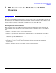
HP Carrier Grade Blade Server bh3710 Overview Front View Front View The components available at the front of this 6 EIA unit high (6U) server are: • Ten individual Compact PCI slots supporting defined configurations for 1-slot and 2-slot PCAs • Vertical cooling fan tray with slot status LEDs on the bulkhead • Two hot swap n+1 power supplies Figure 1-1 8 Blade Server Front View Chapter 1
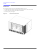
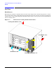
HP Carrier Grade Blade Server bh3710 Overview Rear View Rear View The components available at the rear of this 6 EIA unit high (6U) server are: • Two hot swap N+1 inlet modules • 10 individual Compact PCI slots supporting defined configurations for blades Figure 1-2 Chapter 1 Blade Server Rear View 9
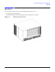
HP Carrier Grade Blade Server bh3710 Overview Air Flow Air Flow Blade Server The Blade Server utilizes a right-side front to left side back cooling scheme. Six fans integrated on a vertical tray cool the system. Refer to Appendix A for System Specifications. Air enters the vent along the right front and side surface of the chassis and passes through the front and rear card cage, then travels out through the left rear and side surface.
HP Carrier Grade Blade Server bh3710 Overview Air Flow Power Supply Each power supply contains cooling fans. Cool air flows through each power supply from front to back. Because they are separated by the solid bottom of the card cage, power supply air and blade server air do not mix.
HP Carrier Grade Blade Server bh3710 Overview System Backplane System Backplane The passive system backplane is located in the Blade Server to accommodate front and rear blades. Ten Compact PCI slots are located on each side. Figure 1-5 Blade Server Backplane, rear view Figure 1-6 Blade Server Backplane, front view DC Power Supplies Two power supplies and two power cords ship with each system.
HP Carrier Grade Blade Server bh3710 Overview DC Power Supplies Both modules reside in the lower bay of the chassis. They are accessed from both the front and rear of the chassis as illustrated in Figure 1-7 and Figure 1-8. Each power supply has two visible LEDs that display operating conditions: • A green LED illuminates whenever DC power is present and within operating specifications.
HP Carrier Grade Blade Server bh3710 Overview DC Power Supplies • A yellow LED illuminates whenever the power supply is in a fault condition.
HP Carrier Grade Blade Server bh3710 Overview DC Power Supplies Figure 1-8 Chapter 1 HP Blade Server DC Power Supply (front view) 15
HP Carrier Grade Blade Server bh3710 Overview bp2200 Server Blade bp2200 Server Blade The Blade Server contains one bp2200 server blade that comes factory installed and is pre-configured with HP-UX. The bp2200 server blade is double-wide and resides in slots 1 and 2. A label matches the blade to the chassis slot with the logo shown in the figure below.
HP Carrier Grade Blade Server bh3710 Overview Installing Optional Fibre Channel (FC) Disk Carriers Installing Optional Fibre Channel (FC) Disk Carriers Additional storage capacity for server blades can be added using the FC disk carrier with one or two additional drives installed. The carrier and drives utilize two slots and can be installed in slots 3/4, 5/6, and 7/8. Slots accommodating FC disk carriers are identified by the symbol below.
HP Carrier Grade Blade Server bh3710 Overview Fan Assemblies The two systems are separate and do not provide cooling for each other. See figure below for airflow information.
HP Carrier Grade Blade Server bh3710 Overview Server Blade Fan Tray Server Blade Fan Tray The Server Blade Fan Tray is a single unit located in a vertical housing on the right side of the Blade Server front. The Tray must be removed and replaced within 20 seconds to keep the system from shutting down. Fans in the Tray are not individually replaceable.
HP Carrier Grade Blade Server bh3710 Overview Power Supply Fans Power Supply Fans Power Supply Fans are integral to the power supply and can only be changed by removing and replacing the power supply. Figure 1-15 Power Supply Fans Power Supply Cooling Fans Slot Blockers Any slot that is not occupied by a blade must contain a slot blocker to channel cool air in the proper direction and to maintain the cooling system pressure.
HP Carrier Grade Blade Server bh3710 Overview Blade Server Racking Information Blade Server Racking Information The racking kit enables the installation of the bh3710 chassis into a rack. Rack kit installation documentation is shipped with each server inside the rack kit box. Racking information may also be found at the Web site at: http://www.hp.
HP Carrier Grade Blade Server bh3710 Overview Blade Server Racking Information 22 Chapter 1
2 General System and Facility Guidelines This chapter provides general computer facility guidelines for planning and preparing the site. Careful site planning and preparation ensures trouble-free installation and reliable operation of HP Blade Servers. Factors that may contribute to less than optimal equipment operation are also highlighted. Refer to Appendix A-3 for more information on guidelines specific to the Blade Server.
General System and Facility Guidelines Electrical Load Requirements (Circuit Breaker Sizing) Electrical Load Requirements (Circuit Breaker Sizing) Appendix A summarizes electrical power load (KVA input) requirements for this HP server but additional capacity should be added for equipment upgrading or expansion.
General System and Facility Guidelines Distribution Hardware Precautions have been taken during power distribution system design to provide immunity to power outages of less than one cycle. However, testing cannot conclusively rule out loss of service. Therefore, adherence to the following guidelines provides the best possible performance of power distribution systems for HP server equipment: • Dedicated power source—Isolates server power distribution system from other circuits in the facility.
General System and Facility Guidelines Grounding Systems Grounding Systems Power Distribution Safety Grounding The power distribution safety grounding system consists of connecting various points in the power distribution system to earth ground using green (green/yellow) wire ground conductors. Having these ground connections tied to metal chassis parts that may be touched by computer room personnel protects them against shock hazard from current leakage and fault conditions.
General System and Facility Guidelines Grounding Systems Cabinet Performance Grounding (High Frequency Ground) Signal interconnects between system cabinets require high frequency ground return paths. Connect all cabinets to site ground. NOTE In some cases power distribution system green (green/yellow) wire ground conductors are too long and inductive to provide adequate high frequency ground return paths.
General System and Facility Guidelines Grounding Systems • Good—Use the raised floor structure as a ground grid. In this case, the floor must be designed as a ground grid with bolted down stringers and corrosion resistive plating (to provide low resistance and attachment points for connection to service entrance ground and HP server equipment). The use of conductive floor tiles with this style of grid further enhances ground performance.
General System and Facility Guidelines System Installation Guidelines System Installation Guidelines This section contains information about installation practices. Some common pitfalls are highlighted. Both power cable and data communications cable installations are discussed. NOTE In domestic installations, the proper receptacles should be installed prior to the arrival of Hewlett-Packard equipment. Refer to the appropriate installation guide for installation procedures.
General System and Facility Guidelines Environmental Factors Environmental Factors The environmental factors discussed in this section are: • “Computer Room Preparation” • “Space Requirements” • “Floor Loading” • “Cooling Requirements” • “Humidity Level” • “Dust and Pollution Control” • “Metallic Particulate Contamination” • “Electrostatic Discharge (ESD) Prevention” • “Acoustics” Computer Room Preparation The following guidelines are recommended when preparing a computer room for a HP se
General System and Facility Guidelines Environmental Factors Delivery plans should include the possible removal of walls or doors. The physical dimensions for applicable computers and peripheral equipment are summarized in Appendix A, “System Specifications and Requirements.” Operational Space Requirements Other factors must be considered along with the basic equipment dimensions. Reduced airflow around equipment causes overheating, which can lead to equipment failure.
General System and Facility Guidelines Environmental Factors An appropriate floor system consultant should verify any floor system under consideration for a HP server installation. NOTE Raised Floor Loading Raised floor loading is a function of the manufacturer's load specification and the positioning of the equipment relative to the raised floor grid.
General System and Facility Guidelines Environmental Factors Basic Air Conditioning Equipment Requirement The cooling capacity of the installed air conditioning equipment for the computer room should be sufficient to offset the computer equipment dissipation loads, as well as any space envelope heat gain.
General System and Facility Guidelines Environmental Factors An air distribution system should be zoned to deliver an adequate amount of supply air to the cooling air intake vents of the computer system equipment cabinets. Supply air temperature should be maintained within the following parameters: • Ceiling supply system—From 55° F (12.8° C) to 60° F (15.6° C) • Floor supply system—The recommended air intake temperature for the blade server is between 68° F and 77° F (20° C and 25° C) at 90 cfm.
General System and Facility Guidelines Environmental Factors CAUTION Low humidity contributes to undesirably high levels of electrostatic charges. This increases the electrostatic discharge (ESD) voltage potential. ESD can cause component damage during servicing operations. Paper feed problems on high-speed printers are usually encountered in low-humidity environments. Low humidity levels are often the result of the facility heating system and occur during the cold season.
General System and Facility Guidelines Environmental Factors Because metallic particulates conduct electricity, they have an increased potential for creating short circuits in electronic equipment. This problem is exaggerated by the increasingly dense circuitry of electronic equipment. Over time, very fine whiskers of pure metal can form on electroplated zinc, cadmium, or tin surfaces.
A System Specifications and Requirements Table A-1 System Specifications Description Specification Dimensions (H, W, D) 10.5 x 17 x 14 in (26.25 x 42.50 x 35.00 cm) Weight (configured) approximately 51 lbs (23.4 Kg) Input Power Operational: Recommended: -40 to -70 VDC (Margin included) -48 to -60 VDC Temperature Operational: Non-Operational: +5 to +35C.
System Specifications and Requirements Table A-2 Power Consumption (Maximum) (Continued) VAa Power Required Power Supply 750.0 Watts a. These wattage values are used to perform the calculations in Table A-3, “Power Consumption and Air Conditioning Requirement Summary.” Table A-3 Power Consumption and Air Conditioning Requirement Summary Component Quantity Chassis 1 HP Server bp2200 1 FC Storage Blade Multiply Qty. by VA Value Power Dissipated Air Conditioning Required 0.0 Watts 0 89.
B Power Plug Configuration The power cable designed for the DC Blade Server is shown below. Figure B-1 bh3710 DC Power Plug The end of the power cable where the male plug goes will be unterminated.
Power Plug Configuration 40 Appendix B
C Conversion Factors and Formulas These conversion factors and formulas will assist in data calculation for systems that do not conform specifically to the configurations listed in this Site Preparation Guide. Conversion factors used in this document and additional conversion factors that may be helpful in determining factors required for site preparation are provided. Conversion Factors Refrigeration 1 watt = .86 kcal/h 1 watt = 3.412 Btu/h 1 watt = 2.
Conversion Factors and Formulas Formulas Formulas KVA =Voltage x Current (amps) Watts =VA x PF BTU =Watts x 3.
Glossary Apparent power A value of power for AC circuits that is calculated as the product of RMS current times RMS voltage, without taking the power factor into account. ASHRAE Standard 52-76 Industry standard for air filtration efficiency set forth by the American Society of Heating, Refrigerating, and Air-Conditioning Engineers, Inc. ASL Above sea level. Btu/h The abbreviation for British thermal units.
Glossary PCI PCI Currently, the most popular local I/O bus, the Peripheral Component Interconnect (PCI) bus was developed by Intel and introduced in 1993. power consumption that a customer will most likely experience and can use for power budgeting purposes. PICMG A consortium of companies involved in utilizing PCI for embedded applications. The PCI Industrial Computer Manufacturers Group (PICMG) controls the PICMG specification.
Index A acoustics, 36, 37 altitude, maximum, 37 American Society of Heating, Refrigerating, and Air-Conditioning Engineers, Inc.
Index O online uninterruptible power supply (UPS), 25 overview, 7 P peripheral component interconnect (PCI), 44 power consumption, 37 panel, 26 quality, 24 supply, 11, 12 supply fans, 20 system protection, 24 power factor, definition, 44 power plug configuration, 39 power supply labeling, 37 printed circuit assembly (PCA), 43 printed circuit board (PCB), 43 R raceway systems, 25 racking kit, 21 raised floor, 27, 32 raised floor metal strip ground system, 28 refrigeration conversion factors, 41 rigid conduit