H Broadband Service Analyzer Setting Up the STM-1 Electrical Interface Pod
Copyright Notice Warranty Printing history © Hewlett Packard Australia Ltd 1996 All rights reserved. The information contained in this document is subject to change without notice. HEWLETT-PACKARD MAKES NO WARRANTY OF ANY KIND WITH REGARD TO THIS MATERIAL, INCLUDING, BUT NOT LIMITED TO, THE IMPLIED WARRANTIES OF MERCHANTABILITY AND FITNESS FOR A PARTICULAR PURPOSE.
Contents Guide to the HP E5200A Broadband Service Analyzer Documentation ........ About the STM-1 Electrical Interface Pod....................................................... Online Help ........................................................................................................ To Access User Online Help......................................................................... Front Panel at a Glance ....................................................................................
Guide to the HP E5200A Broadband Service Analyzer Documentation Guide to the HP E5200A Broadband Service Analyzer Documentation The HP E5200A Broadband Service Analyzer comes with a comprehensive set of paper and online documentation. Use the following table to determine which documents you should use.
About the STM-1 Electrical Interface Pod About the STM-1 Electrical Interface Pod Overview The HP E5123A STM-1 Electrical Interface Pod is a self-contained, plug-in module. You use it in conjunction with the HP E5200A Broadband Service Analyzer to test and analyze a system under test (SUT).
Online Help Online Help The User Online Help provides all the information you need to use the analyzer. Use the following sections to learn how to perform tasks: • • • • • • Getting started Monitoring Capturing Running tests Simulating System administration Use the Reference section to find information about framing formats, alarms, errors, and measurements. To Access User Online Help There are four ways to access information in the User Online Help.
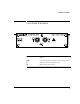
Front Panel at a Glance Front Panel at a Glance Access (green LED) Lights each time the interface pod is accessed by the network. Signal (yellow LED) Lights when a valid signal is present at the input connector. In (BNC) Accepts an electrical signal from the SUT. Out (BNC) Provides a signal to the SUT.
To Set Up the Interface Pod To Set Up the Interface Pod Caution Handle the interface pod with care to avoid electrostatic discharge (ESD) damage during unpacking, installation, and operation. The connectors on the front and rear of the interface pod are susceptible to ESD. 1 Insert the interface pod into the analyzer. See “To Insert the Interface Pod” on page 5. The procedure is the same for all interface pods. 2 Connect the interface pod to the SUT. See “To Connect to the System Under Test” on page 6.
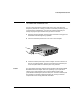
To Set Up the Interface Pod To Insert the Interface Pod You can insert and remove interface pods at any time, even when the analyzer is powered on. Initially, you insert an interface pod when you set up the analyzer. Subsequently, you insert an interface pod when you change the physical layer interface that you want to monitor. 1 Hold the interface pod with the front panel connectors facing you and the Hewlett-Packard logo facing upwards. 2 Insert the interface pod into Port 1 or Port 2 of the analyzer.
To Set Up the Interface Pod To Remove the Interface Pod Gently press on the clip underneath the interface pod and pull the interface pod out of the analyzer. When you remove the interface pod, make sure you store it in a dust free location that meets the environmental requirements listed in “Environmental Specifications” on page 13. An electrostatic-safe bag has been supplied for the storage of each interface pod.
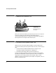
To Set Up the Interface Pod Receive (Rx) Transmit (Tx) Receive (Rx) Common system connections and test connections are • • • non-intrusive system connection—T-piece and passive test connections intrusive system connection—network element, remote loopback, and in-line test connections diagnostic system connection—transmit loopback and external loopback test connections See the HP E5200A Broadband Service Analyzer User’s Guide or the User Online Help for details about these system connections.
To Set Up the Interface Pod Automatic Configuration Parameters After you insert the interface pod and connect it to the SUT, the analyzer automatically configures to the STM-1 electrical signal. The analyzer sets the remaining physical layer receive and transmit parameters to the following defaults: • • • See also 8 reference (internal) clock 20 dB input gain off full duplex User Online Help contains information about the ATM layer automatic configuration parameters.
To Set Up the Interface Pod To Manually Configure the Interface Pod 1 From the Configure menu, select the appropriate port; then select Set Up. 2 Click the STM-1 tab. 3 Select the parameters you require. 4 Click to set the configuration or Click Auto to set the parameters to the default settings. A message warns you that the reconfiguration will cause some measurements and data to be lost and asks if you want to continue. Click OK.
What to Do Next What to Do Next The interface pod is now ready for use. See the User Online Help to find out the different tasks you can perform using the analyzer and interface pod.
Standards and Specifications Standards and Specifications Communications Standards ITU-T G.703 Physical/Electrical Characteristics of Hierarchical Digital Interfaces ITU-T G.708 Network Node Interface for the Synchronous Digital Hierarchy ITU-T G.709 Synchronous Multiplexing Structure ITU-T I.432 B-ISDN User-Network Interface—Physical Layer Specifications ITU-T G.825 The control of jitter and wander within digital networks which are based on the synchronous digital hierarchy ATM Forum UNI 3.
Standards and Specifications Input and Output Specifications Transmit Levels Parameter Nominal Min. Max. Signal level 1.0 V (pp) 0.9 V (pp) 1.1 V (pp) Line rate 155.52 Mb/s –4.6 ppm +4.6 ppm Line jitter Notes complies with ITU-T G.703 using internal frequency reference complies with ITU-T G.825 (SDH), Bellcore GR-253-CORE, and Bellcore TR-TSY-000499 (SONET) Receive Levels Parameter Sensitivity Line rate 12 Nominal Min. Max. 13 dB 155.52 Mb/s –15 ppm Notes complies with ITU-T G.
Standards and Specifications Physical Specifications Weight 1.0 kg ( 2.2 lbs) (nominal) Dimensions Height: Width: Length: 44 mm (1.73 inches) 149 mm (5.87 inches) 222 mm (8.74 inches) not including front panel connectors 236 mm (9.29 inches) including front panel connectors Environmental Specifications Parameter Nominal Min. Max.
Certification Hewlett Packard Australia Ltd certifies that this product met its published specifications at the time of shipment from the factory. Hewlett-Packard (HP) further certifies that its calibration measurements are traceable to the extent allowed by the calibration facilities of other International Standards Organization members. Warranty The hardware is warranted against defects in materials and workmanship.
Warnings DO NOT operate damaged equipment Whenever it is possible that The following general safety precauthe safety protection features built into this tions must be observed during all product have been impaired, either through phases of operation, service, and physical damage, excessive moisture, or repair of this product.
Avertissement Service et ajustement Cet appareil répond aux normes de la “Classe de sécurité 1” et est muni d’un fil de mise à la terre pour votre protection. Des “tensions dangereuses” résident dans cet appareil. Par conséquent, le service et l’ajustement doivent être effectué uniquement par une personne qualifiée. Pour prévenir les risques de choc électrique, la broche de mise à la terre du cordon d’alimentation ne doit pas être désactivée.
Right top margin for modules DECLARATION OF CONFORMITY According to ISO/IEC Guide 22 and EN 45014 body text drop Manufacturer’s Name Hewlett Packard Australia Ltd Manufacturer’s Address Australian Telecom Operation 347 Burwood Highway Burwood East 3151 Victoria, Australia declares that the product: Product Name STM-1 Electrical Interface Pod Model Numbers HP E5123A Product Options This declaration covers all options of the above product.
Left top margin for modules inner margin for text and artwork body text left margin hanging column right margin page inner margin body text drop body text bottom margin footer rulling line footer text base line
Right top margin for modules outer margin for text and artwork body text left margin hanging column right margin page inner margin body text drop body text bottom margin footer rulling line footer text base line
Left top margin for modules inner margin for text and artwork body text left margin hanging column right margin page inner margin body text drop body text bottom margin footer rulling line footer text base line