
HP StorageWorks Enterprise Modular Library E-Series 71e Getting Started (AH876-96004, November 2008)


8
8
10
1
2
3
4
5
6
7
9
Plug an Ethernet cable (included) into the
Ethernet port on the interface controller (middle
card) and into the TO FIBRE CHANNEL
C
ONTROLLERS port on the Interface Manager
card (bottom card in the card cage).
Plug an FC cable (not included) into the FC0 port
on the interface controller (middle card) and into
either the host bus adapter (HBA) port on a host
or into an FC switch that is connected to the host.
LTO3 tape drives only: If a second host is
available, plug an FC cable (not included) into
the FC1 port on the interface controller (middle
card) and into the HBA port on the host or into
an FC switch.
Plug an Ethernet cable (included) into the
CASCADE port on the Interface Manager card
(bottom card) and into the PUBLIC port on the
library robotics controller (top card in the card
cage).
Plug an Ethernet cable (not included) into the
NETWORK port on the Interface Manager card
(bottom card) and into the Ethernet port on your
management station.
Plug each power supply into a power strip
(power cord included). Plug each power supply
into a different power strip. You cannot plug the
power supplies directly into the wall outlet.
If it’s not already plugged in, plug each power
strip into the rack’s power distribution unit (PDU).
And plug the PDU into an AC outlet. If you have
more than one power distribution unit (PDU),
plug each PDU power cord into a different AC
power circuit to establish redundancy.
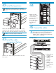
Make the following connections. Attach labels to the
ends of each cable.
LTO3 tape drives only: Plug an FC cable
(included) into the FC port on a tape drive and
into a TD# port on the interface controller
(middle card in the card cage). Repeat for each
tape drive.
LTO4 tape drives only: Plug an FC cable
(included) into the FC Port A on a tape drive and
into the SAN. Repeat for each tape drive.
LTO4 tape drives only: Plug an Ethernet cable
from the MGMT port on the tape drive to the
switch for the internal network. Plug in the tape
drives in order starting with the top tape drive
going to port 1 on the switch.
LTO4 tape drives only: Plug an Ethernet cable
from port 24 on the switch for the internal
network to one of the TO FIBRE CHANNEL
CONTROLLERS ports on the Interface Manager
card (bottom card in the card cage).
1. Switch for the internal network
2. Library robotics controller
3. e2400-FC 2Gb interface controller
4. To host
5. Interface Manager card
6. To management station
7. Port A to SAN
8. Tape drives
9. To port 1 on the switch
10. To port 2 on the switch
LTO4 tape drives