
HP StorageWorks Enterprise Modular Library E-Series Getting Started (AD560-96069, May 2010)

IMPORTANT:
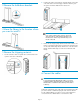
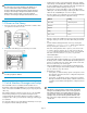
The robot cannot access tape cartridges in the bottom one or
two rows of the bottom module in the library. If the bottom
module is a tape drive expansion module or capacity expansion
module, do not insert tape cartridges into the bottom row. If the
bottom module is a base module or card cage expansion
module, do not insert tape cartridges into the bottom two rows.
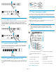
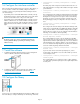
14 Power on the library
1. Close the center door of the library and turn the centerdoor knob
one-quarter turn clockwise to lock it.
2. At the back of the library, turn on the main power switch.
NOTE:
Your library might look different.
15 Initial Interface Manager card setup
If an IPv4 DHCP network is available and the fault LEDs are not
illuminated, verify that the NETWORK port on the Interface Manager
card is connected to that DHCP network for proper setup. Skip the rest
of this step.
If the Interface Manager card does not have access to an IPv4 DHCP
network during initial power up, the Interface Manager must be
configured manually. The Interface Manager card will not enable or
configure its eth0 or eth1 ports until it knows which type of library type
it is installed in.
You will need a DB9 to 3-pin serial cable from the library accessory kit
to configure the Interface Manager manually.
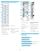
• Verify that the operator control panel displays an HP logo, that the
robotic library controller (RLC) LED is flashing, and that the fault LED
for each installed tape drive is illuminated. The LEDs will remain illu-
minated until the Interface Manager card is set up.
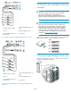
• Plug the 3-pin connector of the DB9 to 3-pin serial cable into the
SERIAL port on the Interface Manager card. Plug the DB9 end of the
cable into the serial/COM port of a server or laptop.
• From the computer, open a terminal session to the Interface Manager
card using the following terminal configuration settings:
SettingAttibute
Autoband, 9600Baud Rate
8Data bits
1Stop bit
NoneParity
NoneFlow control
• Once the computer has established a serial connection to the Interface
Manager card, log in with the user name admin and password ad-
min.
• Note the Interface Manager firmware revision by executing the
command show firmware revision, and the system date and
time by executing the command show mgmt clock.
If the IM is running firmware l232 or previous, enter service mode
to continue; otherwise, skip this step. To enter service mode, type
service at the CLI prompt and enter the current service password.
If the date on the IM is still set to 1/1/2001, use password
3FV6Y043FAUV8N.
• Execute the command set network config eml
• Wait until the RLC and drive fault LEDs are no longer illuminated and
the library starts to initialize. If the RLC fault LED is flashing after five
minutes, turn off the main power switch. Wait several seconds and
then turn on the main power switch again.
• When the RLC fault LED is not longer flashing, both Ethernet ports
on the Interface Manager card should be properly configured and
you can continue to set up the network.
• Configure the IP settings:
• If using IPv4, use either the library operator control panel or Inter-
face Manager card serial connection to configure the static/manu-
al IP address settings.
• If using IPv6, use the library operator control panel or Interface
Manager command line interface (CLI) to enable IPv6. Once IPv6
is enabled, use the Interface Manager CLI to configure IPv6 basic
settings.
NOTE:
If the library is only connected to an IPv6 network, the Interface
Manager card and library firmware versions must support IPv6.
If the Interface Manager card or library firmware versions do
not support IPv6, connect and configure the library and Interface
Manager card to an IPv4 network, update the firmware, and
then connect and configure the library and Interface Manager
card for IPv6.
Page 5